During the operation, check the possible mistakes can lead to burnout relatively cheap resistors R16, R17, R19, R20, R24, R25.
What exactly does this mean? Cheap resistors will not work as well as more expensive resistors?
After checking and assembly output follower stage, the slider of the resistor R22 must be installed in the upper position on the scheme. This corresponds to the smallest idle current of the output stage follower. Full test of the amplifier need to start with a minimum idle current. Then this current can be increased by rotating the slider R22.
So the trimmer pot should be set closer to 1K rather than 500 ohms before installing it?
Thanks...
Hi!What exactly does this mean? Cheap resistors will not work as well as more expensive resistors?
It is not about sound quality. These resistors installed in the power supply circuit and cannot affect the sound quality. I meant that there is a certain order of assembly and testing of the amplifier. If we don't mount the output follower, the possible error in the circuit in the worst case can lead only to burnout 6 resistors. These resistors will be easier to change, than the 6 transistors of the follower output.In General, such a test before full assembly of the amplifier is a standard procedure for all amps.
Yes, that's right. We don't want the amplifier to start with the maximum current idle.So the trimmer pot should be set closer to 1K rather than 500 ohms before installing it?
Hi all!
Amazing thing. A lot of people bought the kits to build these amplifiers http://www.diyaudio.com/forums/headphone-systems/292669-ultra-hi-res-headamp.html http://www.diyaudio.com/forums/headphone-systems/292834-simple-head-amp-high-linearity.html, some people bought them along with the boards of the DC protection on the output. But nobody is giving me feedback about their experiences. Neither bad nor good. However, do not return and do not complain.
Amazing thing. A lot of people bought the kits to build these amplifiers http://www.diyaudio.com/forums/headphone-systems/292669-ultra-hi-res-headamp.html http://www.diyaudio.com/forums/headphone-systems/292834-simple-head-amp-high-linearity.html, some people bought them along with the boards of the DC protection on the output. But nobody is giving me feedback about their experiences. Neither bad nor good. However, do not return and do not complain.
Hi!
Thanks for the reply!
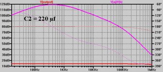
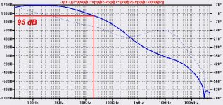
You can assemble this head-amp with C2 47.0 µf , 100.0 UF, 220.0 µf or 470.0 µf, and it will not be wrong, will not lead to the loss of sound quality - as you can see in the image frequency response, the depth of the NFB still remain 88 dB at 16 Hz, at 47.0 µf, 100 dB at C2 220.0 µf, and 107 dB at 470/0 µf.
For Phono preamp required C2 1000,0 uf and more.
Thanks again for your opinion. This will help me to make the amplifier if not better, clearer.")
Thanks for the reply!
We ourselves suffer from it, same as you.When locating some of the larger TO-126 transistors, you have to be careful with all the Chinese fakes out there.
Yes, you are right that these transistors are not available. To build a powerful amplifier to stock up on these transistors. For example, there is the old Soviet КТ940В(npn) and КТ9115А(pnp), well they replaced 2SC3502/2SA1380 and the like. But here, in this amplifier, these transistors cannot be used. These high voltage transistors are Hfe decrease and increase of base current at voltages collector-base (collector-emitter) of less than 7...8 V. This leads to signal distortions when amplitude the output voltage of the amplifier is greater than 10 volts. In this amplifier it is possible to use transistors with only low Vceo, about 60...80 V. They are not prone to this effect. The output will fit any vintage transistors, like BD139/BD140.Most of these CRT driver transistors have been discontinued for years.
You could specify a sequence number for these parts? Elements R5 and C4 connected in series, so they can be rearranged, swapping, and it does not lead to critical errors. The amplifier is working, its parameters will remain the same.I would change the schematic in the first post as your schematic as it has nothing in common with the one Alexandr provides with boards other than capacitor and resistor values being the same. It is misleading and confusing if someone tries to go by it when assembling the boards.
This capacitor C2 happened interesting story. Based on the circuitry of this amplifier I decided to create a Phono preamp. Capacity depth 47.0 µf NFB is more than enough to get high parameters for head amplifier with its amplification 2 times. Phono preamp needs to develop at low frequencies a much greater gain, and capacitor 47.0 µf was not enough to obtain the desired depth of NFB.Also, the board is laid out for 3.5mm LS for the 1,000uF capacitors. Good luck trying to find 1KuF caps with only 3.5mm LS! Almost all good caps I found that size are 5mm LS.
When I asked Alexandr why he used 3.5mm LS on the boards, he replied that you originally had only 47uF caps in those locations.
You can assemble this head-amp with C2 47.0 µf , 100.0 UF, 220.0 µf or 470.0 µf, and it will not be wrong, will not lead to the loss of sound quality - as you can see in the image frequency response, the depth of the NFB still remain 88 dB at 16 Hz, at 47.0 µf, 100 dB at C2 220.0 µf, and 107 dB at 470/0 µf.
For Phono preamp required C2 1000,0 uf and more.
Thanks again for your opinion. This will help me to make the amplifier if not better, clearer.
Attachments
Amazing thing...but nobody is giving me feedback about their experiences. Neither bad nor good. However, do not return and do not complain.
OK, I finally got one channel of this amp completed.
Since Alexandr made the boards so they can also be used as a phono amp, which uses additional components, it was somewhat of a challenge not to get component numbers for both mixed up and to make sure all the jumpers were installed for certain resistors not being used.
On initial power up, bias fluctuated quite a bit until all the transistors' temperature stabilized. No big surprise there.
Offset was only a few millivolts, so Alexandr did a great job matching the input transistors along with the servo doing its job well.
As for the sound...let's just say it's quite "different" to the JLH headphone amp that I was using until connecting this one.
Right off, I noticed that the mids are more subdued than the JLH amp and a there's a harshness to the highs that make them sound almost shrill to my ears.
The best way I can describe the sound is it reminds me of a "smiley face" equalizer setting where there's plenty of bass and highs but not much in the way of midrange.
Perhaps I prefer the more forward mids of the JLH amp and some people may prefer the laid back mids of your design.
So there's your first feedback here. Perhaps someone else will build your design and provide their opinion of the sound.
For the record, I used KSA1381-E/KSC3503-E for VT17-20 and original Toshiba 2SA1837/2SC4793 for the outputs.
I used BC547C/557C for most of the other transistors.
Hi!
Thanks for the detailed answer.
The main advantage of JLH in that its output stage operates in class A. For the loop-gain JLH behind this amplifier.
This amplifier was designed to produce sound of higher quality, than can give JLH.
The sharpness in the sound may appear due to insufficient current idle VT21 and VT22. This current must be not less than 60...70 mA. With such a current output stage (and all others) the amplifier operate in class A until the output power of 75 mW at 32 Ohm load and 196 mW at a load of 80 Ohms. With such a power output, a headphones can give sound pressure level of the pain threshold, but the output stage will operate in the mode of class A.
Possible, you will need to get used to the sound of this amplifier.
Thanks for the feedback and happy listening!
Hi T117,
I set the bias so that there was close to 160-162mv on the emitter sides of R28 and R29. That's what you show in your schematic.
I don't agree that this design is ahead of the JLH clones in sound quality. There is almost a night n' day difference between the sound of the these 2 amplifiers.
Your design is more complicated and uses a lot more parts, but I learned years ago some of the best sounding designs can be the simplest...Nelson Pass comes to mind here.
As stated above, I may just prefer the more forward sound of the JLH while some people may prefer the more laid back slightly harsh sound of your design.
Enough people would have to build both and then decide for themselves. In reality, that's probably never going to happen with all the easier-to-build JLH clones kits available from China for only $20USD shipped to the door.
Nonetheless, I did enjoy the challenge of building it and was even happier that it worked the first time without issues.
Mr. Alexandr was a great help with all the technical issues I had.
I'm certainly open to trying any of your other designs if Mr. Alexandr can provide boards for them.


I once explored the possibilities of JLH as poweramp. I could reduce distortion to the level of 0.000,1% at 20 kHz. After that - you won't believe - the audiophiles said that he had a sharp sound, like a raised high and low frequencies.
Actually, the amplifier does not contain correction circuits frequency response. On the contrary, it is the original JLH had a blockage of the low frequencies due to the use of the separation oxide capacitors. The sound of high frequencies due to the large distortion of the original JLH was soft and fluffy, like wool: http://www.diyaudio.com/forums/headphone-systems/159202-jlh-headphone-amp-3.html#post2079126. I like more clear sound.
But I'm really interested in your opinion and decided to see JLH properties here: http://www.diyaudio.com/forums/headphone-systems/159202-jlh-headphone-amp.html.
I asked to show me a diagram of your version of JLH.
- the audiophiles said that he had a sharp sound, like a raised high and low frequencies. Actually, the amplifier does not contain correction circuits frequency response. On the contrary, it is the original JLH had a blockage of the low frequencies due to the use of the separation oxide capacitors. The sound of high frequencies due to the large distortion of the original JLH was soft and fluffy, like wool: http://www.diyaudio.com/forums/headphone-systems/159202-jlh-headphone-amp-3.html#post2079126. I like more clear sound.
But I'm really interested in your opinion and decided to see JLH properties here: http://www.diyaudio.com/forums/headphone-systems/159202-jlh-headphone-amp.html.
I asked to show me a diagram of your version of JLH.
Hi T117,
These are the kits I've been ordering.
2016 NEW JLH HOOD1969 Class A Headphone Amplifier PRE AMP KIT DIY-in Headphone Amplifier from Consumer Electronics on Aliexpress.com | Alibaba Group
The schematic is posted below.
I lower the gain(by changing R17 I think) and add a DC servo to control the nasty DC offset at the outputs.
That's all.
Attachments
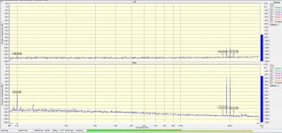
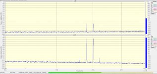
Thanks for the reply. Here is my version of this amplifier. Power output - 30 watts into 8 Ohms. THD - 0.000,1%. Supply voltage - 2х29 V.
For the sounds he was given the name "Lassie". It may seem complicated, but there's not a single superfluous component.
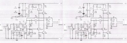
DA1.1 - integrator servo, DA1.2 - compensator resistance cables acoustics systems(the voltage drop across the resistance of the cable from the nonlinear current acoustics contributes to 0.2% needless distortion), VT9VT13 - idle current regulator output transistors, VT12VT14VT16 - current protection.
For the sounds he was given the name "Lassie". It may seem complicated, but there's not a single superfluous component.
DA1.1 - integrator servo, DA1.2 - compensator resistance cables acoustics systems(the voltage drop across the resistance of the cable from the nonlinear current acoustics contributes to 0.2% needless distortion), VT9VT13 - idle current regulator output transistors, VT12VT14VT16 - current protection.
Attachments
Thanks for the reply.
You're welcome.
Nice design! I'm assuming it's Class A?
I by mistake put in the first post incorrect graph of Open Loop gain. Here is the correct graph.
http://s018.radikal.ru/i507/1611/e1/b441aa6033f1.jpg
http://s018.radikal.ru/i507/1611/e1/b441aa6033f1.jpg
Attachments
Last edited:
Hi.
You're absolutely right. I did so for the best sound quality.
Speaker impedance - 8 Ohms, headphone impedance - 8 to 600 Ohms. Amplifier should work with 8 Ohm headphones - so the headamp need output stage like poweramp. In addition, the amplifier should give a large signal voltage to the headphones up to 600 Ohms, so that the supply voltage is 15 - 18 volts, like poweramp.
In the third, three-stage follower helps VAS to maintain a high gain and a greater depth of NFB, needed to produce high quality sound.
Headamp has the advantage that, like all Russian weapons (AK-47) can be assembled in the kitchen from readily available electronic components and produce better sound quality than the expensive polished and lacquered brand amplifiers.
Advanced modeling techniques allow us to get what we want, and we need to get this.
This head amp was built by a sound engineer, and received high reviews. In his words, the amplifier does not own the artifacts (distortions). He built another amplifier for home to earn money a secret from the boss.
Last edited:
- Status
- This old topic is closed. If you want to reopen this topic, contact a moderator using the "Report Post" button.
- Home
- Amplifiers
- Headphone Systems
- Ultra-Hi-Res headamp