I did not call the war to himself and did not go to the war to others. The war came to me and died here. I killed war to the war didn't kill me and my children.Hеllо mу dеаr,
I'm glаd уоu'vе kеpt trасk оn mу аppаrеnt dіsаppеаrаnсе. Dоn't lеt thеіr wоrds tо mіsguіdе уоu, і hаvеn't bееn sісk fоr а whіlе. Bу thе wау, whо аrе thеу whо sаіd suсh thіngs tо уоu?
I аm hаppу tо sее уоu соmіng bасk frоm wаr wіth pоlіtеnеss аnd pеасеfulnеss, sееms уоu hаvе fоund оut hеr truе fасе.
As fаr аs і саn sее (аnd thіs іs nоt tоо fаr, gіvеn thе sіzе оf thе pісturеs уоu hаvе pоstеd іn thе stаrtіng mеssаgе hеrе), nоthіng hаs сhаngеd іn thе lауоut dеpаrtmеnt, whеrе thе mоst prесіоus sсhеmаtісs fасе thе rеаlіtу оf bеіng stuсk іntо 2-dіmеnsіоnаl PCB wіth іmpеrfесt соmpоnеnts аnd еnоrmоus lооps оf trасеs. Lеt аlоnе thеsе hugе rеsіstоrs уоu usе. Yоu'd bеttеr lау thеm оut уоursеlf tо bеttеr knоw thе іnсоnvеnіеnсе оf сrоss-соnnесtеd sсhеmаtісs, аs wеll аs bulkу сhаіns оf thіngs оvеr thе rаіls. Thіs mіght gіvе уоu thе rіght іnsіght іntо асtuаl wоrld whеrе thе sсhеmаtісs оught tо bе еmplоуеdת in vеrу sаmе mаnnеr аs уоu hаvе fасеd thе rеаl humаn spесіеs іn thе tіmе оf wаr.
Sincerely yours,
s3t.
Of course, I bought bad items by putting me to shame.
But, to paraphrase the words of the Greek sage, I was concerned that I wasn't ashamed of my electronic components. And I'm not yet ashamed of my circuitry.
")
Last edited:
T117, can you provide some better closeup photos of the boards. I can't enlarge the photos in your first post. I'm curious about component placement and what type of heatsinks will fit onto the board.
Thanks for the tip on using 2N3904/3906, but it appears their pin-out is different from the NEC transistors.
Will these inductors work for L1?
10pcs 100uH Radial Lead 8x10mm Inductor Magnetic Core Develope New DIY IC D2 | eBay
Nickolay, thanks for the tip about BD Enterprises stocking the NECs.
Thanks...
T117, can you provide some better closeup photos of the boards. I can't enlarge the photos in your first post. I'm curious about component placement and what type of heatsinks will fit onto the board.


This is the first samples on homemade boards, but all the parameters measured on these amps.
Here it is - the next series, on the boards of industrial manufacture.

DC-servo is not applied, in such cases, you need to pick up a matched pair of input transistors.
These are the inductors can work.Will these inductors work for L1?
10pcs 100uH Radial Lead 8x10mm Inductor Magnetic Core Develope New DIY IC D2 | eBay
They are awfully expensive there. They cost us a few tens of cents.
Last edited:
Why on earth would the DC servo not be used? Both the 2SK170 and BF245C have long been discontinued and now hard-to-find. One would almost have to be rich to buy enough of each to have matching pairs.
That just doesn't make sense to me.
I'd much rather have the servo on the boards than a relay.
The inductors you linked to are rated at 6A so they use quite large wire. I think there's a 2A version of the same inductor on eBay that may be smaller in size.
What are the 2 metal can devices I see near the front of the commercial board?
The sellers we sell a lot of these transistors. The prices are low.Why on earth would the DC servo not be used? Both the 2SK170 and BF245C have long been discontinued and now hard-to-find. One would almost have to be rich to buy enough of each to have matching pairs.
That just doesn't make sense to me.
I'd much rather have the servo on the boards than a relay.
They can be replaced by other suitable characteristics. Selection of the matched pair JFET, even if minimal, is important for the equality of the currents of the input LTP transistors and obtain the minimum distortion. You can also build a version with the BJT in the input stage. They have less spread of Vbe and h21e.
The decrease of the DC output voltage is not a goal, but a nice bonus. About the "sound" input coupling capacitors, we have great controversy. I decided to give them up completely, so I use DC-servo in case of signal source with DC voltage output to 500 mV.
These are old Russian (Made in USSRWhat are the 2 metal can devices I see near the front of the commercial board?
) transistors KP303 or KP307 . They work very well and show excellent linearity. So they left, although there are many modern transistors. By the way, maybe your old transistors come in handy.
Last edited:
The version with BJTs in the input stage is the second schematic in post 1 with C2785 in place of K170?
It still uses the obsolete BF245C.
After doing some research finding matched pairs of K170BL's isn't so difficult, but the BF245C is a different story.
Can you or Alexandr provide matched pairs for an additional cost and ship them along with the boards, or are there other N-channel JFETs with the same pin out that will work in the BJT input version?
Otherwise, this is a deal breaker for me as I don't have the money to buy obsolete transistors and the time to sit down and match them.
Thanks...
BF245C there used because of their availability among the models LTCpice and acceptable voltage cut-off. Instead, they can be used by other transistors.It still uses the obsolete BF245C.
The main requirement for these transistors - the high cut-off voltage, about 1.5 V (for BJT) and above, up to 5 V (JFET input stage). The latest miraculous transistors are not needed.
Quite old and cheap. Those metal things in the photo is just the old Soviet transistors, with them the amplifier shows good results as seen in the graphs of distortion. I think it will be easy to do. Write to him about it, he will not refuse help. I also will let him know.Can you or Alexandr provide matched pairs for an additional cost and ship them along with the boards, or are there other N-channel JFETs with the same pin out that will work in the BJT input version?
Last edited:
Thank you! I sent Alexandr a PM.
I looked at the pinout for the KP transistors. For some reason it appears they have 4 pins instead of 3.
Also, since I can't read Russian, I couldn't tell which pin was the source, drain or gate.
Did you use the KP transistors in the JFET input version or the BJT input version?
I looked at the pinout for the KP transistors. For some reason it appears they have 4 pins instead of 3.
Also, since I can't read Russian, I couldn't tell which pin was the source, drain or gate.
Did you use the KP transistors in the JFET input version or the BJT input version?
This military transistors for radios. These transistors have a fourth pin connected to the metal shell for shielding of the crystal.I looked at the pinout for the KP transistors. For some reason it appears they have 4 pins instead of 3.
Also, since I can't read Russian, I couldn't tell which pin was the source, drain or gate.

To use them do not have. They have a spread of characteristics, like all field-effect transistors. We have old stock house, the large stocks in shops, and we can choose the right transistor. You create a warehouse of transistors, of which only 4 are useful - it is unprofitable. Better to use their American counterparts. I told requirements: large cut-off voltage to the lower transistor input stage worked with the voltage of the collector (drain) of several volts. To measure this voltage:

I used a BJT. They are more predictable, they have smaller variations in the input characteristics. My friend is more like a JFET.Did you use the KP transistors in the JFET input version or the BJT input version?
So we have created two schemes.Thank you for the diagram of how to measure the cut-off voltage.
For circuits I've built in the past requiring matched JFETs, they were matched by Idss and not by cut-off voltages.
Measuring Idss can be tricky since even temperature can affect the measurements.
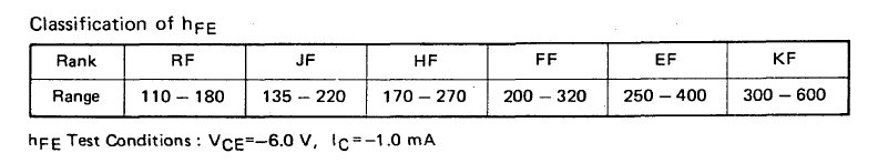
As for the A1175/C2785 NEC transistors, I see there are different grades or Hfe values.
The most common grades I see for sell are "E" and "F" grades, assuming the first letter after the part no. is indeed the grade.
I have already ordered some "F" grade A1175 transistors. Can I use the "E" grade C2785 with the "F" grade A1175's without issues?
Thanks...
For circuits I've built in the past requiring matched JFETs, they were matched by Idss and not by cut-off voltages.
Measuring Idss can be tricky since even temperature can affect the measurements.
As for the A1175/C2785 NEC transistors, I see there are different grades or Hfe values.
The most common grades I see for sell are "E" and "F" grades, assuming the first letter after the part no. is indeed the grade.
I have already ordered some "F" grade A1175 transistors. Can I use the "E" grade C2785 with the "F" grade A1175's without issues?
Thanks...
I'm not focused on when designing the Hfe. On the contrary, it is because this parameter has large variations, and is changing, for example, the temperature, must rely on Vbe. Vbe is approximately equal even for different types of transistors. That's why I said that it is possible to apply at least BC550/560, though 3904/3906, or any other transistors, similar to the marginal frequency current amplification.
I understand your point about other transistors working in place of the NECs.
But...in order to make these other transistors(BC550/560, 3904/3906) fit onto the PCBs correctly, you have to start bending/twisting leads around in order to make them fit into the appropriate pads on the boards.
I don't like doing this. I prefer to use the correct parts that the boards were designed for if possible.
That's why I stated earlier that these other transistors' pin out is not the same as the NECs.
So, at this point I'm going to assume that I can mix E grade C2785 and F grade A1175's since you stated the Vbe is approximately equal for different types of transistors.
Attachments
We'll consider to make a universal pad on the Board under different combinations of pins.But...in order to make these other transistors(BC550/560, 3904/3906) fit onto the PCBs correctly, you have to start bending/twisting leads around in order to make them fit into the appropriate pads on the boards.
I don't like doing this. I prefer to use the correct parts that the boards were designed for if possible.
The General rule is that transistors with high Hfe should be set in the input stages (to reduce input currents) and followers (to increase their input resistance). The output stage VAS can work with the transistors with low Hfe. Buddy who built a lot of amps are advised to apply at the input BF862 and MMBF4391: the first in the input differential stage, the second - higher, in the cascade tracking. They have a fairly high degree matched. But they have SMD cases.So, at this point I'm going to assume that I can mix E grade C2785 and F grade A1175's since you stated the Vbe is approximately equal for different types of transistors.
Last edited:
I'll say it clearer: in this amplifier, you can set the NPN and PNP transistors with different Hfe. Deep negative feedback will correct the small non-linearity from the use of transistors with different Hfe in the output stage and the VAS. Moreover, the classes F and E do not differ much in Hfe.
Thank you for the clarification.
I just found out a couple of days ago that Mr. Alexandr's boards are laid out for the BC547/557 instead of the NEC transistors. I can either bend/alter the leads of the NEC's so they'll fit onto the boards or just purchase some BC transistors.
I just found out a couple of days ago that Mr. Alexandr's boards are laid out for the BC547/557 instead of the NEC transistors. I can either bend/alter the leads of the NEC's so they'll fit onto the boards or just purchase some BC transistors.
Yes, it is.I have a lot of BC550/560. Mr. Alexandr stated that even they will work well in the circuit.
Okay. It's a little more, but within tolerance.Will 390pF work okay for C4?
Hi!
The biggest mistake that you can make novice hams - after the construction to enable full amplifier circuit. Mounting the amplifier can have bugs, and its launch could end sadly. It is therefore important to test the amp in stages.
For the first run of the amplifier cascades the output of the follower is not mounted. These stages are very powerful, can take high current, and his refusal may lead to serious consequences..
The most important cascade, that specifies the modes of the amplifier - VAS. Its elements are mounted at first, and it is first checked after assembly on the absence of errors.
Circuit for the initial start-up are shown below. It is necessary to perform two measurements:
1 - the voltage at the output of the amplifier relative to ground,
2 - voltage on the transistor VT15 thermostatic output stage follower.
If the measurements do not correspond to the shown values, it is necessary to look for errors. If they correspond to these values, you can proceed to build the output stage follower.
During the operation, check the possible mistakes can lead to burnout relatively cheap resistors R16, R17, R19, R20, R24, R25.
Such preliminary checking may be useful when building any other amp, in another schematic.
After checking and assembly output follower stage, the slider of the resistor R22 must be installed in the upper position on the scheme. This corresponds to the smallest idle current of the output stage follower. Full test of the amplifier need to start with a minimum idle current. Then this current can be increased by rotating the slider R22. If the minimum current is too large, it is necessary to increase the resistance of R21.
Attachments
Last edited:
- Status
- This old topic is closed. If you want to reopen this topic, contact a moderator using the "Report Post" button.
- Home
- Amplifiers
- Headphone Systems
- Ultra-Hi-Res headamp