Just a note for builders. I suffered from a quite persistent ground loop problem with my build which was there also with M2X inside the same chassis. I managed to reduce the buzz to a quite low level but it always nagged me and I could hear the buzz when no music when close to speakers. Probably the root cause was me using only one power tranny instead of dual mono plus the combination of the rest of my system.
Anyway, the problem was solved by using the balanced connection from my DAC to the input connection on the UDNeSS board (+Vin, -Vin). What an enjoyable silence even with my ears against the speakers.") Highly recommended if you have a balanced source.
Highly recommended if you have a balanced source.
Anyway, the problem was solved by using the balanced connection from my DAC to the input connection on the UDNeSS board (+Vin, -Vin). What an enjoyable silence even with my ears against the speakers.
Highly recommended if you have a balanced source.~180 compared to J2 residual.
Please observe the alignment negative peaks of residual compared to both positive and negative peaks of the fundamental.
Indra is correct,the Udness is positive phase second harmonic according to the sim supplied.A perfect negative phase second harmonic shows as +90 degrees in the spice error log harmonic number 2 line.I've experimented with circuits to verify this.
Just swap the phase of both signal and speakers if you must.
The input is differential.
Patrick
Thank you.It would be interesting to hear someones impresssions of the difference in sound that swapping the signals makes.
Got a package in the mail yesterday
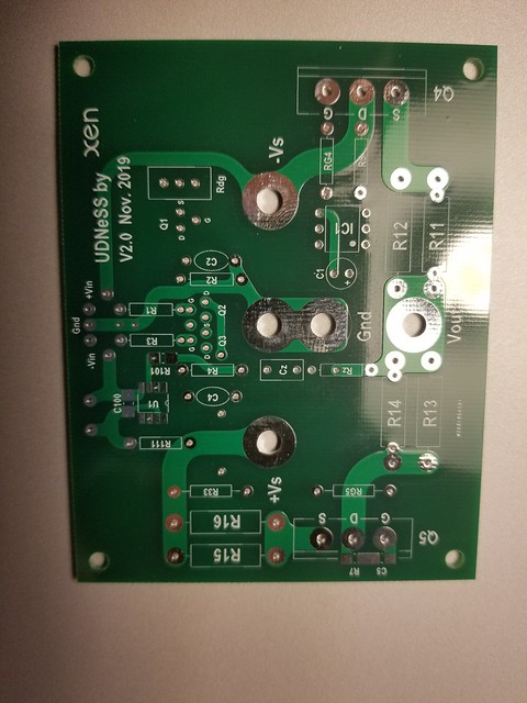
I had held off getting any additional components till I was sure that the boards were in hand - now the real work / fun begins
..dB
Hi dB
Could you please tell me the size of the PCB. I’d like to order some but my on-line viewer does show the dimensions.
Thanks
Eric
My listening impressions in post #130 are with input and output reversed so negative phase H2. After that I changed to balanced input from my DAC. Now the balanced connection is done so that the input is not reversed but I actually forgot to change speaker connections so they are still reversed. I like the sound now very much, but I don't know whether the second harmonic is now positive or negative phase.Thank you.It would be interesting to hear someones impresssions of the difference in sound that swapping the signals makes.
Easy to swap speaker wires polarity though...
Last edited:

Ordering direct from a PCB shop cost much less than 10USD, not ?
It is also for the J2 as in the photo, not the UDNeSS.
PCB Prototype & PCB Fabrication Manufacturer - JLCPCB
Seeed Studio Fusion PCB Assembly - Turnkey Prototype PCB Assembly Service
Cheers,
Patrick
It is also for the J2 as in the photo, not the UDNeSS.
PCB Prototype & PCB Fabrication Manufacturer - JLCPCB
Seeed Studio Fusion PCB Assembly - Turnkey Prototype PCB Assembly Service
Cheers,
Patrick
Hi,
Some small questions here:
1. Can I lower the idle current to, say 200mA to make it Class AB?
2. Can I use 2SK182 (SIT) as Q4 and biasing at 200mA, while Q2/Q3 is P-ch?
3. If SIT is usable, would it be better to replace Q5 and Q4 to 2SK182?
Since Class A generate very huge heat, plus 2SK182 is very valuable, I don't want them running so hot.
Regards,
Erik
People asked about matching.
For best results, you always want to match.
Especially important for Q2,3.
Q1 is not important, as it is only current source and you can trim with Rdg.
Q4, 5 do not have to be matched to each other.
But if you want identical channels, you should match Q5 between channels.
Same for Q4.
Here are some simple matching circuits.
Note that rail voltage is limited by the opamp, as well as some other components in the opamp.
It is also limited by power device dissipation.
Patrick
.
Very basic question, but I can't find another version of this matching circuit that has two voltage sources? Is that correct, that you need 24vDC and 9vDC to match IRFP9240 and J113, or does the model mean that either voltage would work? Trying to get my parts together and this has my head spinning. Was hoping I could buy a lab supply, set the constant current and voltage and then test the MOSFETs. The more I read, the more confused I get if that would work.
I'm sure once I get a jig together and start testing a few mosfets, it will begin to make more sense. I just don't want to buy more than I need, unless it really is necessary.
To build amps in general, you should have a lab aupply that will give you at least +/-24V (adjustable) with adjustable current limits.
In this case, you need 3A minimum. For some other amps in the future, 5A is handy.
This you can use for matching the FQA9P25's.
For matching 2SK209GR's, you need a 9V battery and a SOT23 test socket.
For measuring J113, you can also use the same battery.
If all this is too confusing and difficult for you, why not just join the Group Buy ?
Interest for potential GB for UDNess PCBs and matched FETs.
Patrick
- Home
- Amplifiers
- Solid State
- UDNeSS, or You don't need Semisouth's