Hi gogowatch
Looking at both the before and after pictures, I'm actually not sure I would bother placing 4 more components on the PCB for that!
The ringing is minimal, and unless you see other improvements from adding them, like sound or distortion figures, I would skip it.
But you did a good job at analysing and tweaking
Best regards Baldin")
Looking at both the before and after pictures, I'm actually not sure I would bother placing 4 more components on the PCB for that!
The ringing is minimal, and unless you see other improvements from adding them, like sound or distortion figures, I would skip it.
But you did a good job at analysing and tweaking
Best regards Baldin
Hi gogowatch
Looking at both the before and after pictures, I'm actually not sure I would bother placing 4 more components on the PCB for that!
The ringing is minimal, and unless you see other improvements from adding them, like sound or distortion figures, I would skip it.
But you did a good job at analysing and tweaking
Best regards Baldin
Thanks Baldin. Yes, the difference is minimal. This is an exercise for me to find values in a RC snubber.
Hello Gogowatch,
2 questions:
what tipe of coil is that?
what is the value of C14 and C32.
regards,
savu
Output coil is Sagami 7G17B-220M-R which is the same series used in IRAUDAMP4, 5, 7S, etc. Stay cool all the time.
Both C14 and C32 are 100nF.
Attached is the schematic.
Cheers,
Edit: please note there is a C22 10uF || C14.
Attachments
Last edited:
Did anyone try!
Hi All,
Did anyone try to suppy floating side of IRS2095X from the comparator supply? I mean supplying for eg. LM 311 symetrical +/-10V and tight pin 1 of the IRS2095x to positive rail of the comparator via 47-100R resistor. In that way current consumption on the output of LM311 can be lowered (refering to the orginal shematic from Bender R15/R12 pairs and R12 can be ommited). What do you think or anyone tried it before? Simulation says it will work. But how about the stability?
Best wishes,
IRS2095X Vdd is regulated by an internal shunt zener diodes. 47-100R is too small for this. I think it is better drive this pin by a current source.
Cheers,
Output coil is Sagami 7G17B-220M-R which is the same series used in IRAUDAMP4, 5, 7S, etc. Stay cool all the time.
Both C14 and C32 are 100nF.
Attached is the schematic.
Cheers,
Edit: please note there is a C22 10uF || C14.
Gogowatch .. could you also attach the library parts for lt spice?
regards,
savu
Gogowatch .. could you also attach the library parts for lt spice?
regards,
savu
Here it is.
Cheers,
Attachments
Here it is.
Cheers,
Hi GoGo:
Can you please tell with software is needed to view the files?
Thanks
Raj
Hi GoGo:
Can you please tell with software is needed to view the files?
Thanks
Raj
LTSpice
Hi GoGo:
Can you please tell with software is needed to view the files?
Thanks
Raj
They are ltspice files. Ltspice is available at,
Linear Technology - LTspice IV Downloads and Updates
Cheers,
IRS2095X Vdd is regulated by an internal shunt zener diodes. 47-100R is too small for this. I think it is better drive this pin by a current source.
Cheers,
Ok, I know that it has an internal shunt zener(9.8-10.8V) but what happens when the power supply for comparator has the same value? Do you think 47-100R is still low. Have you ever measure the voltage on the running IRS2095x IC in your application?
Cheers,
They are ltspice files. Ltspice is available at,
Linear Technology - LTspice IV Downloads and Updates
Cheers,
thank you so much!
Can someone explain how?
Hi All,
Finally, I have finished the multi channel car amp desing of the enclosed schematic. The amp is working fine and now only one channel tested with unregulated +/-42V bipolar power supply. The only thing that I dealt with the sw frequency. Normally amps oscillating at 277KHz with the 28uH ferroxcube gapped toroid and 0.68u. However, I swapt R9&R19 from 2K2 to 1K and the frequency increased to 309KHz. Then for test purpose, I put a 1uF 250V cap from output to GND with a cricodile cable and the sw increased to 430KHz as expected. It is normal up to here. But, when i removed the cricodile and paralleled directly 1u by soldering and really suprised. Becasue the sw frequency was 309KHz again. To test, the idea that it was due to the radiated EMI from the cricodile I removed 1u and put the cricodile cable and re measured the sw. It was again 309KHz. Then, I measured the resistance of the cable it was around 3ohms then I put a 2.2 Ohms resistor series to 1u. Then the sw was 430KHz again. All the measurements was same with or without load(8ohm speaker).
The question is this, how it is possible to get these different results? I could not give a meaning to this. Does anybody have an explanation?
Best wishes,
Attachments
I don't know anything about this circuit, but that reminds me of the zobel on the output of Tripath amps. The values varied depending on the Tripath IC used (0.1uf+33R, 0.22uF+16R5, 0.47uF+10R, etc).
Thanks for your reply. But I do not think it is due to the Zobel network. The sw frequency of the UCD amp does not depending on the load actually. There should be some explanation. Is there any idea?
Best wishes.
Here some photos are!
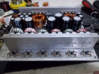
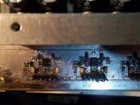
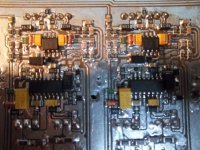
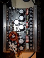
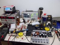
Hi all,
Perhaps some diyers would like to see what the board looks like. I enclosed some photos of the complete board. And I also enclosed the updated schematic of the amplifier. Still waiting for a logical explanation.
Hi all,
Perhaps some diyers would like to see what the board looks like. I enclosed some photos of the complete board. And I also enclosed the updated schematic of the amplifier. Still waiting for a logical explanation.
Attachments
- Status
- This old topic is closed. If you want to reopen this topic, contact a moderator using the "Report Post" button.
- Home
- Amplifiers
- Class D
- UcD like topology amp.