Hi Worthless
Great work.
Could you post your LT sim file and model for IRS20954? ...... thanks in advance ...
About fast comperators. I have tried some different: LT1016, MAX1016, LT1711 and MAX913.
The LT versions uses a bunch of current, which makes PSU difficult if you want to feed it directly from Vcc/Vss through a simple voltage regulator. LT1711 is really fast, and maybe "too fast" as it seems to be very satisfy with a good enough PCB layout.
To me MAX913 is a really good compromise. Very easy to use, and free if you order tham as samples from Maxim
Hi Worthless
Great work.
Could you post your LT sim file and model for IRS20954? ...... thanks in advance ...
About fast comperators. I have tried some different: LT1016, MAX1016, LT1711 and MAX913.
The LT versions uses a bunch of current, which makes PSU difficult if you want to feed it directly from Vcc/Vss through a simple voltage regulator. LT1711 is really fast, and maybe "too fast" as it seems to be very satisfy with a good enough PCB layout.
To me MAX913 is a really good compromise. Very easy to use, and free if you order tham as samples from Maxim
Hi Baldin, sorry for delayed answer. I am really busy with science. If the files are not working that savu already sent, let me to know and thanks to Analogspiceman. By the way if one needs to ask question, please send me an e-mail otherwise, i will probably turn back to you very late.
Yeah i dig the producers web site while i was working on this amp and max913 was one of the best. However, I tried LM311 and get a very good result. Then do not worry about the fast comparator. I used updated PCB for my amp. If you have chance try Bender.ru's version with passive poles on both FB and input. You will see there is no much sonic difference between the comparators. But, passive poles really changes the sonic performance.
Regards
FH
Ir20954s
Hi,
It is shame on International Rectifier because they do not have stock of newer version. I suggest you to use at least IRS20955.If you have option do not use 20954 and prefer to use 20957. But, as i said it is hard to find nowadays. However, Farnell has stock of it in USA. If someone can access to it i am volunteer to buy 10-12 of IRS20957s.
Good luck to you in electronics and good luck to me in fuelcell project!
Regards to all
Dear Bender and all,
I realised that Bender and the others are not interested with the above questions. Anyway! Therefore I tried to make my own desing and get the smallest amp below. Bender, please excuse me if I get you bother by posting in your thread.
First of all simulate the shematic. I used the chip IRS20954S which is known as unsable( Make a diyaudio search) and old IC. I get it from Farnell, it is cheap for now. I did not faced a problem by implementing it. My output mosfets are IRFB5615PBF. SW frequency is 550-600kHz. Input comparator is MXL1016 from Maxim and sound is very good just for my firts testing. DT adj is max(45ns) for first test purpose. I think I have to decrase the sw frequency down to 400k and set the dead time into a suitible time(25ns?).
Regards
NB. If someone interested I can give the PCB toner file
Hi everybody,
Here is the PCB file of the amp. Unfortunately i am far from home and do not have the etched PCB file with me. However while digging my new computer i found a folder wihich was including the backups of my PCB software. I do not have time to complete it again. Although it is not the complete, it is still can be usefull or even can be etched. Please pay attention to the power supply lines if you intend to etch this one. You must ensure a connection from top to bottom copper to get it working properly. Some end corrections may be necessary( a resistor between the ics etc.). If you are not experienced do not try to do it!
Best wishes,
Ferda
Attachments
Yet another version of Cakeamp
Hello All,
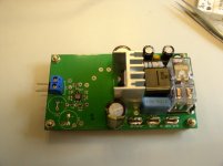
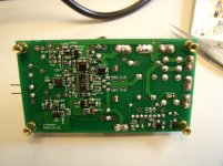
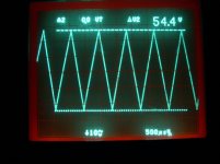
I'm glad that I have made a version of Bender's Cakeamp by modifying the power supply to gate driver, preamp and a DC output protection added. Attached are the traces with no load attached and the amp.
I'm going to post more traces when I have the dummy load.
Cheers,
Hello All,
I'm glad that I have made a version of Bender's Cakeamp by modifying the power supply to gate driver, preamp and a DC output protection added. Attached are the traces with no load attached and the amp.
I'm going to post more traces when I have the dummy load.
Cheers,
Attachments
-
 post-filter-node-input-1k-no-load-1.jpg378.1 KB · Views: 1,118
 -
 post-filter-node-self-oscillate-430R-100pF-no-input-no-load-no-snubber-1.jpg329.7 KB · Views: 1,147
 -
 switching-node-self-oscillate-430R-100pF-no-input-no-load-no-snubber-3.jpg348.1 KB · Views: 1,231
 -
 amp-1.jpg344.1 KB · Views: 1,152
 -
 amp-2.jpg381 KB · Views: 1,149
Yet another version of Cakeamp
Thanks Workhorse and Savu.
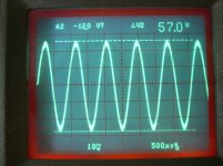
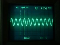
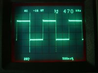
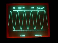
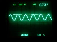
Attached are traces with 4R resistive loading. Switching frequency changed from 470kHz to 510kHz.
Cheers,
Thanks Workhorse and Savu.
Attached are traces with 4R resistive loading. Switching frequency changed from 470kHz to 510kHz.
Cheers,
Attachments
-
 post-filter-node-input-1k-sine-4R-loading-4.jpg298.4 KB · Views: 989
 -
 post-filter-node-self-oscillate-430R-100pF-no-input-4R-loading-no-snubber-1.jpg261.8 KB · Views: 1,036
 -
 switching-node-self-oscillate-430R-100pF-no-input-4R-loading-no-snubber-2.jpg243.8 KB · Views: 1,092
 -
 post-filter-node-input-1k-trig-4R-loading-3.jpg323.7 KB · Views: 960
Super nice work gogowatch. Like the PCB layout a lot 
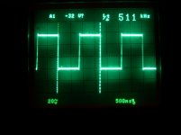
Seems you still have a little bit of ringing on the sqares.
Do you yse subbers on the fets? If so the walues might have to be changed a little to reduce the ringing. But then again, it dosen't seem to be a problem.
Really nice output waveform (55 Vpp is around 95 W in 4 ohm), not bad at all
BR Baldin
Super nice work gogowatch. Like the PCB layout a lot
Seems you still have a little bit of ringing on the sqares.
Do you yse subbers on the fets? If so the walues might have to be changed a little to reduce the ringing. But then again, it dosen't seem to be a problem.
Really nice output waveform (55 Vpp is around 95 W in 4 ohm), not bad at all
BR Baldin
Thanks Baldin.
I have not yet added the snubber and I will do so in the coming week. I'll post result when I have any progress.
Cheers,
Edit: The PCB layout is basically copied from the original Bender's Cakeamp.
Last edited:
Adding snubber for lower mosfet
Thanks Whortless.
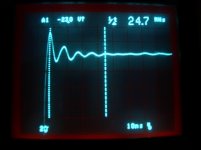
In order to add snubber, I've done some measurement by adding 100pF, 220pF and watch the changes of the ringing signal and then calculate the Resistance and Capacitance in the snubber.
I did it for the lower mosfet snubber first. Following are the traces,
1. Ringing at rising without snubber, 24.7*4 = 98.8MHz
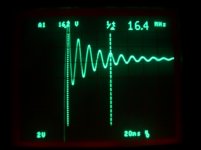
2. Ringing at rising with 100pF, 16.4*4 = 65.6MHz
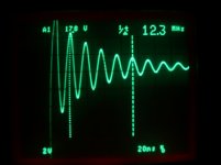
3. Ringing at rising with 218pF, 12.3*4 = 49.2MHz
4. Final rising edge waveform with 218pF+24R
Nice PCB! Congratulations Gogowatch!
Thanks Whortless.
In order to add snubber, I've done some measurement by adding 100pF, 220pF and watch the changes of the ringing signal and then calculate the Resistance and Capacitance in the snubber.
I did it for the lower mosfet snubber first. Following are the traces,
1. Ringing at rising without snubber, 24.7*4 = 98.8MHz
2. Ringing at rising with 100pF, 16.4*4 = 65.6MHz
3. Ringing at rising with 218pF, 12.3*4 = 49.2MHz
4. Final rising edge waveform with 218pF+24R
Attachments
Last edited:
Adding snubber for upper mosfet
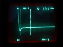
Following are for the upper mosfet,
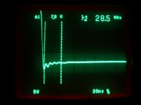
1. Ringing at falling without upper mosfet snubber, 28.5*4 = 114MHz
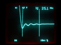
2. Ringing at falling with 100pF, 25.1*3 = 75.3MHz
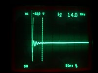
3. Ringing at falling with 218pF, 14*4 = 56MHz
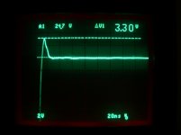
4. Final falling edge waveform with 218pF+18R
Following are for the upper mosfet,
1. Ringing at falling without upper mosfet snubber, 28.5*4 = 114MHz
2. Ringing at falling with 100pF, 25.1*3 = 75.3MHz
3. Ringing at falling with 218pF, 14*4 = 56MHz
4. Final falling edge waveform with 218pF+18R
Attachments
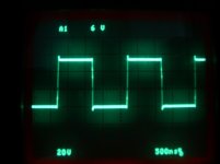
Snubber added
1. Before snubber added.
2. After snubber added.
The snubber killed the ringing but not the overshoot or undershoot. I don't want to change the Rgate at the moment. So I stop the tuning at this point.
Cheers,
Edit: reference http://focus.ti.com/lit/an/slup100/slup100.pdf
1. Before snubber added.
2. After snubber added.
The snubber killed the ringing but not the overshoot or undershoot. I don't want to change the Rgate at the moment. So I stop the tuning at this point.
Cheers,
Edit: reference http://focus.ti.com/lit/an/slup100/slup100.pdf
Attachments

Last edited:
The snubber killed the ringing but not the overshoot or undershoot.
Cheers,
Thats what they do, they eliminate ringing only.
Nice Tweak.....!!!
- Status
- This old topic is closed. If you want to reopen this topic, contact a moderator using the "Report Post" button.
- Home
- Amplifiers
- Class D
- UcD like topology amp.