Dont know, but the difference between 10k and 1 k in noise is small.
I think it isnt worth to add 1 NF, ok with 4,7 nf noise is really goone but the good sound too...
any solutions to kill noise and save the good sound
NMOS: think about the little of what you did, because you don't want to think, just want answers. This is not a way it goes.
As Pafi said you must first realize where noise come from. If you have an oscilloscope measure every point with it if you can.
Class D Amplifier Design Basics II. from IR has a whole Chapter 5 about it. (from page 60 to 70) (you can download it at IRs homepage)
IR gives three headline steps:
1. Minimize noise source in switching stage
2. Maximise noise immunity in analog stage
3. Minimise noise coupling from switching stage to analog stage
Changing input high cut cap is a part os step 2, and it is an easy way if you only want to use the amp as a low-freq amp. But it does not eliminate the source of the problem.
First of all use the oscilloscope to measure the switching. Check for ringing and other transients.
Then check after the filter. There should only a pure sine after it, if there are other, check the components. If you inductor wound in multilayer, then layer-to-layer capacitance can have a significant effect. Check your LC cap, it should have low ESR, low dielectric loss, propylene caps intended for high-freq high-pulse duties is a good way.
Check the feedback path, it shoulld not pick up any interference, check it at the input of the comparator. If it pick up stuff, and you think tha route is optimal, cannot be so much optimal, filter it (page 65). Use a differencial input RFI filter. Set the input RFI filter (the 1nF cap) to have the optimal pass freq.
Check for supply decoupling. There should be ceramic HF filter caps really close to fets, and elcos a bit farer.
What is function of of cap 10uF + 100n from pin 5 to pin 6 of ir2110. And what his minimal value. Can I use on example only 1uF MKT
When the low side FET is on, the IR2110 fills up these caps with the diode. Then it turns off low side fet. Then pin 5 flies up. Then it turns on high side FET, and uses the power in these caps for it.
10uF+100nF has very much extra. I use 1uF 25V X7R ceramic (or 50V Y5V) and it is enough. (you have to fill up about 100nC to 10V, so the FET's gate equals to about a 10nF cap, so minimal cap should be about 100nF to turn on the FET)
So everything >220nF is well enough. (for higher gate charge you need more)
Ok lacy, thanks.
How do you resolve problem with noice in your layout with normal conection of comparator?
I intend to use it as a low-freq amp, so I only increased the input cap. I've busy doing other things, so didn't have time to pay it more attention. Sorry
But:
Even if you increase the cap to 4.7n it should not cut high-freq if you have a source with low output inpedance. On a bode plot 4n7 with 22k input has a -0,5dB (-0,7dB from 100 Ohm source) at 20kHz.
I didn't notice any high-freq loss, since i used a low-output inpedance source. A -1dB at 20kHz is no loss for me.
NMOS: put an omamp input before the amp, then you have a low output-impedance source. Quick solution, not so correct
Thank you very much to Dzony988 and Lorylaci
for help.... have remove "volume potenciometer"
signal comes now directly from PC On Board Soundcard to comparator and Class D Amp sounds fine with clear mid and Highs...great natural sound
Actually have 4,7NF with 100Pf and 22K
will design input op amp circuit with NE5532 next days and test
Finally IR2210 and mosfets are a little (to) warm about 40 degrees with very low output power in the night, is this normally?
switching frequency about 250 KHZ
Mosfets IRFP250N
Rail +/- 85 V DC
Mosfets IRFP250N
The 250 is very capacitive on the gate.
I read somewhere that the 250 is two 240's on the same die hence twice as much capacitnace on teh gate as the 240.
However, 40 degrees doesnt sound too bad.
it is not output power relatedFinally IR2210 and mosfets are a little (to) warm about 40 degrees with very low output power in the night, is this normally?
Thank you very much to Dzony988 and Lorylaci
for help.... have remove "volume potenciometer"
signal comes now directly from PC On Board Soundcard to comparator and Class D Amp sounds fine with clear mid and Highs...great natural sound
Actually have 4,7NF with 100Pf and 22K
will design input op amp circuit with NE5532 next days and test
Finally IR2210 and mosfets are a little (to) warm about 40 degrees with very low output power in the night, is this normally?
switching frequency about 250 KHZ
Mosfets IRFP250N
Rail +/- 85 V DC
I am happy to hear that.
Read the datasheet of IR2110, if you haven't done that. If you have, look at figures 28-32, it shows temperature in the function of switching freq, gate cahrge and gate driving resistors.
If you have time try to figure out the noise source, you should check you switching, your feedpack path. The input rf cap is a quick solution but not so elegant.
Ok thanks for Info...
I hope I dont have missunderstood something,...
after check the datasheet....this means a little hot...about 50 Degress for IR2110 for very low and High Output power too in this amp is normally for IR2110 ?
because I thought.. If feeling IC hot mistake could be in circuit
Last edited:
My ir2110 is littile to warm (45 deegres) and amp work fine. I have tested him even on 2 ohm load on +-70V. In output is irfb4227 (4600pF input capacitance)
-On IRFP240PBF (1300pF input capacitance) and same board with all same components ir2110 is totaly cold..
Operation temeprature of ir2110 can go up to 80deegres without consequences... Am I right?
-On IRFP240PBF (1300pF input capacitance) and same board with all same components ir2110 is totaly cold..
Operation temeprature of ir2110 can go up to 80deegres without consequences... Am I right?
My ir2110 is littile to warm (45 deegres) and amp work fine. I have tested him even on 2 ohm load on +-70V. In output is irfb4227 (4600pF input capacitance)
-On IRFP240PBF (1300pF input capacitance) and same board with all same components ir2110 is totaly cold..
Operation temeprature of ir2110 can go up to 80deegres without consequences... Am I right?
NMOS, according to the Datasheet your junction temperature should be about 70°C, so 40-50°C at the case is normal. See figure 30. and ffigure 31.
Max junction temperature for IR2110 is 150°C, so a case temperature up to 70-80°C is quite normal.
Not input capacitance but gate charge, gate resistance, and the gate resistor what matters. Supply voltage also has some effect on it, but switching freq is the most important.
I intend to use it as a low-freq amp, so I only increased the input cap. I've busy doing other things, so didn't have time to pay it more attention. Sorry
But:
Even if you increase the cap to 4.7n it should not cut high-freq if you have a source with low output inpedance. On a bode plot 4n7 with 22k input has a -0,5dB (-0,7dB from 100 Ohm source) at 20kHz.
I didn't notice any high-freq loss, since i used a low-output inpedance source. A -1dB at 20kHz is no loss for me.
NMOS: put an omamp input before the amp, then you have a low output-impedance source. Quick solution, not so correct
please check schematic
Balanced low output-impedance source with op amp, R14 goes to amp input
could this work wit6h UCD amp without High and mid loss and could be the values from devices ok ?
Attachments
-On IRFP240PBF (1300pF input capacitance) and same board with all same components ir2110 is totaly cold..
I have used 2110 with IRFP250's and it didnt get hot despite 250's having twice the gate charge of the 240.
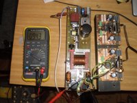
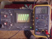
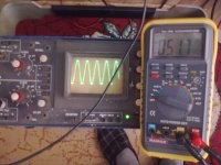
First test")
which inductor do you use ? Model and supplier ?
- Home
- Amplifiers
- Class D
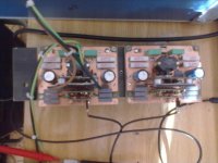
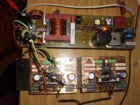
- UCD 25 watts to 1200 watts using 2 mosfets