put in a fast fuse or use overcurrent protection or both..
Fuse itself is stupid. Fast blowing fuse is stupider.
Useing fuse for overcurrent protection is not a go. Music signal is peaky, load is variant (if you have a nominal 4 Ohm load, that can be even 2 Ohm at impedance minimum - bandbass cabinets and tapped horns usually), so you have to put in much larger fuses than needed (if you plan a 400W @ 4 ohm amp, you need to put in >20A fast blowing fuses not to false trigger), than it even won't protect at a slight short. Fuse will go weak form start-on current of caps, and from high peak currents, and it will fail with time, even when there is no overcurrent or short circuit.
Useing crowbar protection with normal or slow blowing fuses rated properly (not to false trigger), is a way to go.
That happened to me twice.
When i turned on the amp specialy Q4 and Q2 were burned,also the ir2110.
While I was measuring resistance on each pin I discovered that pin COM and VDD were shorted ,also Hin with vss with a resistance of 40ohms.
In other ir2110 ic burned. Pins VDD and Hin were shorted with a resistances of 80ohms.
So
I have all fake ir2110 chips. Some of them burned quickly and others didn´t resist at high level voltages.
The originals have a laser print , it haven´t ink or something like that and have other code like the pics showed below.
I discovered it by tacatomon.
because He saw the ir2110 that i used in the amp and he explained me all about these fakes ics. Also there some posts about this in this thread.
My ics haven´t lote code only the ir2104 that i own
It is possible that you have fake ICs. Buy them from a distributor with greater reputation (it will be more expensive, but you will sure get real ones).
Also it is possible you have missed something. So when powering on put a bulb or a 22-100 Ohm >5W resistor in series with the supply lines. I always do it on first tries, it will protect the FETs or other stuff if there is a short somewhere (then you just have to play icy-cold-warm-hot to find out where)
Yesterday night I got an idea before sleeep. In the level shifts current generator, if you put a zener in series with the R6 (and change it to for example 10k), then you have an undervoltage protection ")
It is very simple, its kind of trivial, but it works very well in simulations. It also can decrease start up transients from power supply, since it does not start oscillation until supplies are rised enough.
I've got an idea for overvoltage protection too:
It is also very simple, and its kinda' trivial, it also works very well in simulations. It will turn off both fets, and if you put two resistors parallel with them it will divide supply voltage to two so it may not exceed fets voltage ratings.
An externally hosted image should be here but it was not working when we last tested it.
It is very simple, its kind of trivial, but it works very well in simulations. It also can decrease start up transients from power supply, since it does not start oscillation until supplies are rised enough.
I've got an idea for overvoltage protection too:
An externally hosted image should be here but it was not working when we last tested it.
It is also very simple, and its kinda' trivial, it also works very well in simulations. It will turn off both fets, and if you put two resistors parallel with them it will divide supply voltage to two so it may not exceed fets voltage ratings.
Yesterday night I got an idea before sleeep. In the level shifts current generator, if you put a zener in series with the R6 (and change it to for example 10k), then you have an undervoltage protection
An externally hosted image should be here but it was not working when we last tested it.
It is very simple, its kind of trivial, but it works very well in simulations. It also can decrease start up transients from power supply, since it does not start oscillation until supplies are rised enough.
I've got an idea for overvoltage protection too:
An externally hosted image should be here but it was not working when we last tested it.
It is also very simple, and its kinda' trivial, it also works very well in simulations. It will turn off both fets, and if you put two resistors parallel with them it will divide supply voltage to two so it may not exceed fets voltage ratings.
undervolttage and overvoltage you are great,....are you sure its working in real music condition ?
but overcurrent protection against short circuit is important....can you add ?
undervolttage and overvoltage you are great,....are you sure its working in real music condition ?
but overcurrent protection against short circuit is important....can you add ?
Well I don't think its so important. It is so important to you, use the trivial solution of a shunt resistor.
I am working on current transformer idea, but will try it next weekend.
I have one question!?
In full bridge desing, in this situation, which will be value for Cf capacitor?!
And is my amp good if it has 250KHz swich freq.
Thanks
It depends on whether you use AD or BD modulation. If you bridge these two modules then you don't need additional Cf. If you redesing it to full-bridge, wuth AD modulation, then you can add Cf. For more details, see this link http://focus.ti.com/lit/an/sloa119a/sloa119a.pdf
Thank you lacy!
What overload protection do you use with sunt resistor? Can you post?
I don't use it, because I want to get up with something other. I have my idea (the current transformer), but I need to test it.
Using a shunt resistor is kinda' trivial. I'm sure you can figure it out... (hint: for low side you need only two transistors)
UCD don't work
Dears DZONY988, LORYLACI, NMOS
My plans are link/archive in the page 2 this forum.
When the UCD is no IR2110 and FETs (only /LM311N and 2N5401) I connect to RCA input a audio signal from my CD player and there is PWM signal from LM311N, perfect!
Also, in the COLECTORs of 2N5401, no problem.
The "crash" happen when it's IR2110 (no fake) and FETs in the place.. terrible!!
Now, I do another test with FQA11N90 but when I switch on the AMP only the 2N5401 (Q1) blowed.
I don 't connect the power supply directly to 120ACV, I use a interconnection series-lamp (40W) but the devices are burned too.
There is not any mistake, I look all many times.
I build very very SMPS and I know so much the IR2110 mosfet driver but the only thing that in my mind is maybe the DEAD TIME is so short and damage this devices..
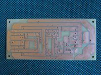
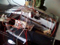
I post here some pictures for you.
Thank by comments.
Sandro
Dears DZONY988, LORYLACI, NMOS
My plans are link/archive in the page 2 this forum.
When the UCD is no IR2110 and FETs (only /LM311N and 2N5401) I connect to RCA input a audio signal from my CD player and there is PWM signal from LM311N, perfect!
Also, in the COLECTORs of 2N5401, no problem.
The "crash" happen when it's IR2110 (no fake) and FETs in the place.. terrible!!
Now, I do another test with FQA11N90 but when I switch on the AMP only the 2N5401 (Q1) blowed.
I don 't connect the power supply directly to 120ACV, I use a interconnection series-lamp (40W) but the devices are burned too.
There is not any mistake, I look all many times.
I build very very SMPS and I know so much the IR2110 mosfet driver but the only thing that in my mind is maybe the DEAD TIME is so short and damage this devices..
I post here some pictures for you.
Thank by comments.
Sandro
Attachments

Dears DZONY988, LORYLACI, NMOS
My plans are link/archive in the page 2 this forum.
When the UCD is no IR2110 and FETs (only /LM311N and 2N5401) I connect to RCA input a audio signal from my CD player and there is PWM signal from LM311N, perfect!
Also, in the COLECTORs of 2N5401, no problem.
The "crash" happen when it's IR2110 (no fake) and FETs in the place.. terrible!!
Now, I do another test with FQA11N90 but when I switch on the AMP only the 2N5401 (Q1) blowed.
I don 't connect the power supply directly to 120ACV, I use a interconnection series-lamp (40W) but the devices are burned too.
There is not any mistake, I look all many times.
I build very very SMPS and I know so much the IR2110 mosfet driver but the only thing that in my mind is maybe the DEAD TIME is so short and damage this devices..
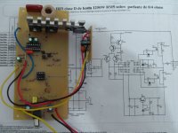
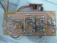
I post here some pictures for you.
Thank by comments.
Sandro
You are mistaken...
This is an UcD amp, so if you take IR2110 out there should not be oscillation, so there is no PWM at LM311 output. That's not a PWM you are talking about, thats only the compared signal, it has nothing to do with PWM. Check it with an oscilloscope, it wont be at arond n*100kHz.
Connect the two main supply lines to the board with 20-100 Ohm 5W resistor (i use 47 Ohm 5W for this), it willl protect the fets in case of cross-conduction.
What is you supply voltage?
I'd also improve the PCB design, yours is far from optimal, even the original PCB design is better.
And why are you using 5W resistors for gate drive? 0,25W should be enough, and they seems to be wire-wound resistors (with high parasitic inductances), change them to cheap carbon film or metal film at once!
Last edited:
Yesterday night I got an idea before sleeep. In the level shifts current generator, if you put a zener in series with the R6 (and change it to for example 10k), then you have an undervoltage protection
you are realy estupid man
It seems nice in simulations. Current generator only supplys current to the differential pair when supply reaches a treshold.
Why do you think its stupid?
@CHACALPOWERS
You have mestake somewhere. This amp is good (with some modification) and its builded hundred of times, but in the begin use low volatage (on example +-30...+-40V) and try with original PCB desing. For that low voltages try with IRF540z even IRFP240. Near fets under the board use elkos 470uf from power rails to gnd. Use original values frst from table
You have mestake somewhere. This amp is good (with some modification) and its builded hundred of times, but in the begin use low volatage (on example +-30...+-40V) and try with original PCB desing. For that low voltages try with IRF540z even IRFP240. Near fets under the board use elkos 470uf from power rails to gnd. Use original values frst from table
I have tested it and it works but there's one problem: whenever I turn it to half the power I get lots of cipping, any idea where's the problem at?
What do you mean by half the power?
What are your supply rails, and at what power (voltage output RMS or peak) does it start clipping?
Cliping indicator is very sensitive and show clip even if you have oscilation in power supplay (transformer or other). Somethimes when is low volateg in my house or my fother turn on the drill, on low power cliping is turn on because his drill is very old and bad and AC voltage has oscilations. In the night wen all is turn on, or in day when my fother not driling everything is ok.
What is your supplay? If you have +-60V, cliping is on 40VAC on output because that cliping indiactor has 3VDC ref (resistror R2).
40VAC on output * 1,41 = 57VDC + 3V ref = 60V of your voltage rail.
That means when amplifier reaches 40VAC on output that is very close to clip and clipping led is turn on, your input potenciometar need not be on the maximum, it depends on the input voltage and gain of amlifier.
Play 1KHz signal from your PC, on the output put multimeter on AC voltage and measure on which voltage cliping led is turn on! Calculate and if something is wrong (on example it shuld turn on led on 40VAC and it turn on on 35VAC) then tell me!
Regards
@Laci
Laci I need your help!
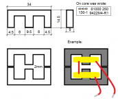
I need for tomorow evening amplifier urgently(+-70V). I found ferrite core (on the picture) with this dimensions, I dont know what is it and material number but very carefully with grinder I maked 2x1mm gap, and now I have 2mm gap and on exaple picture I drew how i want to put the wire.
I dont know how meny turns that i need for 20-22uH. Pleas help.
Thank you
Laci I need your help!
I need for tomorow evening amplifier urgently(+-70V). I found ferrite core (on the picture) with this dimensions, I dont know what is it and material number but very carefully with grinder I maked 2x1mm gap, and now I have 2mm gap and on exaple picture I drew how i want to put the wire.
I dont know how meny turns that i need for 20-22uH. Pleas help.
Thank you
Attachments
- Home
- Amplifiers
- Class D
- UCD 25 watts to 1200 watts using 2 mosfets