Almost done, still haven't figured out that AC connection, probably goes straight to the secondary of mains transformer...
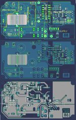
The new pcb will have the dzony's protection part..
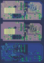
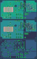
Dimentions are 96mm * 45mm
The layout is not the best. One of the supply lines makes a loop around the comparator part. The other still goes straight next to them. Imagine the current path from power supply to speaker. Then imageine your right hand there, and check the induced magnetic field. It points right through the comparator part.
So this way there will be high noise, in the most sensitive part.
Lay the power lines so, that these high currents should flow next to less sensitive parts. The loop should newer contain noise sensitive parts.
Yes, AC conector goes to secondary of main transformer!
Relay will not turn on if you don have AC. On AC conector use 1N4007 and dont use 470nF, its bad, use 1uF 100V elko but be careful on polarity because on AC conector goes AC voltage from transformer and after 1N4007 its NEGATIV volatage, so negative pin of 1uF elko goes to R6 and positive pin goes to GND.
R6 has 0,5mA curent
so for example +-50V (50V / 0.5mA = 100Kohm)
Relay will not turn on if you dont have KTY81-122 sensor, but its D class amp, temp sens is not need if you have good heatsink and output coil.
If you conect short 1 and 2 conectors without sensor relay will turn on, if you don, relay will not turn on and protection led is turn on. That I want to use for overload protection with sunt resistor and mini relay (everuthing is ok, mini relay is turn on and have short conect to 1 and 2 pins, Amp is overload -shunt resistors turn of mini relay, 1 and 2 dont have conection and main relay is turn off, but temp led now have name overload") )
)
If you have problem with cliping indicator (on example its show clip on 30VAC and true clip is on 38VAC), add before 1K resistor from amp before diodes 1N4004 10K trimer and calibrate him to show true clip (use osciloscope and constant signal, when sine is in clip, calibrate the trimer to turn on cliping led) but use R2 value from table that I post
Good luck
Regards
Relay will not turn on if you don have AC. On AC conector use 1N4007 and dont use 470nF, its bad, use 1uF 100V elko but be careful on polarity because on AC conector goes AC voltage from transformer and after 1N4007 its NEGATIV volatage, so negative pin of 1uF elko goes to R6 and positive pin goes to GND.
R6 has 0,5mA curent
so for example +-50V (50V / 0.5mA = 100Kohm)
Relay will not turn on if you dont have KTY81-122 sensor, but its D class amp, temp sens is not need if you have good heatsink and output coil.
If you conect short 1 and 2 conectors without sensor relay will turn on, if you don, relay will not turn on and protection led is turn on. That I want to use for overload protection with sunt resistor and mini relay (everuthing is ok, mini relay is turn on and have short conect to 1 and 2 pins, Amp is overload -shunt resistors turn of mini relay, 1 and 2 dont have conection and main relay is turn off, but temp led now have name overload
)If you have problem with cliping indicator (on example its show clip on 30VAC and true clip is on 38VAC), add before 1K resistor from amp before diodes 1N4004 10K trimer and calibrate him to show true clip (use osciloscope and constant signal, when sine is in clip, calibrate the trimer to turn on cliping led) but use R2 value from table that I post
Good luck
Regards
Last edited:
I forgot, on relay coil pins you can use led - named Active (show when relay is turn on), but from R5 to raley track use 2.2Kohm resistor and after him conect + of led, - of led conect to colector of BC639.
I atached new schematic in protection.zip with all changes that i told you!
I atached new schematic in protection.zip with all changes that i told you!
Attachments
I used 24V 2x16A relay (coil is 1Kohm).That is important to calculate R5
Relay:
24V 1Kohm coil (24V / 1Kohm = 24mA)
(Supplay Voltage - 24V) / 24mA = R5 in Kohms
on example:
(60V-24v)/ 24V= 1.5K
36Vdrop * 24mA = 864mW resistor, but I use 5W always
I dont know can you use smd resistors because R1..R8 must be 2W, for +-90v must be 5W, exept R3, btw you have all power dispiations of resistor in table
If you use relay with other resistion coil, measure resistion first and calculate values for R5
Last edited:
I will use a 48V relay. Coil is 4kOhm so the current is 11.5mA.
So I will need a 820R resistor which will dissipate around 0.1W so 1206 SMD resistor should be enough. By the way I won't put an active LED because the voltage will be around 50V and current limiting resistor will dissipate too much power..
So I will need a 820R resistor which will dissipate around 0.1W so 1206 SMD resistor should be enough. By the way I won't put an active LED because the voltage will be around 50V and current limiting resistor will dissipate too much power..
Finished. I have uploaded eagle files. Feel free to make changes.. Also there is a drill marker that somehow got in the wrong place of the board, anyhow I'll post the results of the amp soon..
Attachments
Last edited:
2N5401 burning...
Hi ClassDbuilders
I'm trying to build this UCD amplifier but always when I switch on 3 or all 4 2N5401 are damaged and also the IR2110 and fets
I use +40/-40VDC rails, IRFB4227, IR2110, LM311N. I don 't understand what is happen with my UCD amp... somebody can help me? All comments are welcome.
Excuse me by "rough" english.
Sandro from Brazil
As Dzony said, please post you plans. If you do so then we can help.
Its 99% that you misconnected something, or you have designed something bad on your schematic/layout.
Hi ClassDbuilders
I'm trying to build this UCD amplifier but always when I switch on 3 or all 4 2N5401 are damaged and also the IR2110 and fets
I use +40/-40VDC rails, IRFB4227, IR2110, LM311N. I don 't understand what is happen with my UCD amp... somebody can help me? All comments are welcome.
Excuse me by "rough" english.
Sandro from Brazil
Yes please post.....and it can be ... you have fake / counterfeit devices
That happened to me twice.
When i turned on the amp specialy Q4 and Q2 were burned,also the ir2110.
While I was measuring resistance on each pin I discovered that pin COM and VDD were shorted ,also Hin with vss with a resistance of 40ohms.
In other ir2110 ic burned. Pins VDD and Hin were shorted with a resistances of 80ohms.
So
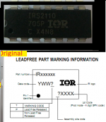
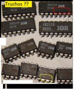
I have all fake ir2110 chips. Some of them burned quickly and others didn´t resist at high level voltages.
The originals have a laser print , it haven´t ink or something like that and have other code like the pics showed below.
I discovered it by tacatomon.
because He saw the ir2110 that i used in the amp and he explained me all about these fakes ics. Also there some posts about this in this thread.
My ics haven´t lote code only the ir2104 that i own
When i turned on the amp specialy Q4 and Q2 were burned,also the ir2110.
While I was measuring resistance on each pin I discovered that pin COM and VDD were shorted ,also Hin with vss with a resistance of 40ohms.
In other ir2110 ic burned. Pins VDD and Hin were shorted with a resistances of 80ohms.
So
I have all fake ir2110 chips. Some of them burned quickly and others didn´t resist at high level voltages.
The originals have a laser print , it haven´t ink or something like that and have other code like the pics showed below.
I discovered it by tacatomon.
because He saw the ir2110 that i used in the amp and he explained me all about these fakes ics. Also there some posts about this in this thread.
My ics haven´t lote code only the ir2104 that i own
Attachments
Last edited:
Yes, AC conector goes to secondary of main transformer!
Relay will not turn on if you don have AC. On AC conector use 1N4007 and dont use 470nF, its bad, use 1uF 100V elko but be careful on polarity because on AC conector goes AC voltage from transformer and after 1N4007 its NEGATIV volatage, so negative pin of 1uF elko goes to R6 and positive pin goes to GND.
R6 has 0,5mA curent
so for example +-50V (50V / 0.5mA = 100Kohm)
Relay will not turn on if you dont have KTY81-122 sensor, but its D class amp, temp sens is not need if you have good heatsink and output coil.
If you conect short 1 and 2 conectors without sensor relay will turn on, if you don, relay will not turn on and protection led is turn on. That I want to use for overload protection with sunt resistor and mini relay (everuthing is ok, mini relay is turn on and have short conect to 1 and 2 pins, Amp is overload -shunt resistors turn of mini relay, 1 and 2 dont have conection and main relay is turn off, but temp led now have name overload
If you have problem with cliping indicator (on example its show clip on 30VAC and true clip is on 38VAC), add before 1K resistor from amp before diodes 1N4004 10K trimer and calibrate him to show true clip (use osciloscope and constant signal, when sine is in clip, calibrate the trimer to turn on cliping led) but use R2 value from table that I post
Good luck
Regards
have you any idea to add short circuit protection for this amp ?
That happened to me twice.
When i turned on the amp specialy Q4 and Q2 were burned,also the ir2110.
While I was measuring resistance on each pin I discovered that pin COM and VDD were shorted ,also Hin with vss with a resistance of 40ohms.
In other ir2110 ic burned. Pins VDD and Hin were shorted with a resistances of 80ohms.
So
I have all fake ir2110 chips. Some of them burned quickly and others didn´t resist at high level voltages.
The originals have a laser print , it haven´t ink or something like that and have other code like the pics showed below.
I discovered it by tacatomon.
because He saw the ir2110 that i used in the amp and he explained me all about these fakes ics. Also there some posts about this in this thread.
My ics haven´t lote code only the ir2104 that i own
That happened to me too, watch that marking stuff or you may end up with shorted pins!
Some time ago I bought similar mosfet driver ICs and only one of them appeared to be working..
Last edited:
have you any idea to add short circuit protection for this amp ?
put in a fast fuse or use overcurrent protection or both..
- Home
- Amplifiers
- Class D
- UCD 25 watts to 1200 watts using 2 mosfets