A buffer goes AFTER a source that cannot adequately drive the cables and receiver.
If you add an attenuator and that attenuator cannot drive the subsequent output then the buffer is after the attenuator not before and not between it.
Andrew, I think we are talking about different things here. I was writing about a crossover like the one in post #43 (which is quite similar to the "passive-buffered" B1-crossovers in this and in other threads). There is a buffer (T5/T6 resp. T9/T10) between the HP/LP filter and the attentuator for the HP/LP section to decouple the filter from the impedance of the attentuator.
Regards
Flo
Hi,
exactly the same logic applies.
The buffer is after the source (filter) if the source (filter) cannot drive the cables (PCB traces) and receiver (pot).
You are not putting a buffer in front of the attenuator.
You are effectively adding a buffer after the filter.
The result, in this case, is the same. But in many cases folk get mixed up because they apply the wrong logic.
no.You are effectively adding a buffer after the filter.
He is adding a buffer after the filter because the filter cannot adequately drive the receiver (PCB traces and pot).
The result, in this case, is the same. But in many cases folk get mixed up because they apply the wrong logic.
I did not get that you were criticising the terminology resulting from the logic, I thought you were pointing to an other schematic.
Sorry - thank you for the clarification.
Regards
Sorry to all to labour that point,
A buffer has a particular job and it has a particular location.
These two conditions for the correct use of a buffer must never be overlooked.
Many who do overlook those conditions put them in the wrong locations that does not solve the basic problem: The source must be capable of driving the receiver, if not, then add a buffer to the source.
Hi Andrew,
nothing happened!
The problem of my understanding was, that some time ago, before the publication of the B1 article, I begun to design a crossover like that with another type of buffer but without this buffer after the filter. I solved the problem of too low Rs in the filter and/or very high values for the attentuator by adding the buffer "in between" the filter and the att to "decouple" those two impedances.
Thats not the right expression from an engineering point of view but it was my logic then. And so it stayed "in between" in my mind
Have a nice evening
So you are saying that there is no need for a buffer between the HP/LP filter and the attentuator?
Sorry for the late reply - overlooked the post. The buffer has to be there, without the crossover would not work appropriately.
Sorry for the late reply - overlooked the post. The buffer has to be there, without the crossover would not work appropriately.
Ok, I was thinking fast, as you said, AndewT tried to explain the correct use-meaning of a buffer!
By the way, in my schematic resistors are 10K and 100K are these values ok or I should try smaller values?
Ok, I was thinking fast, as you said, AndewT tried to explain the correct use-meaning of a buffer!
By the way, in my schematic resistors are 10K and 100K are these values ok or I should try smaller values?
Depending on the chosen XO frequency - "strange" R values are easier to get than "strange" Cs - you can choose whatever you want. But I would not go much lower than 5k (4,7k is o.k.) for the smaller R, the larger value should be 10x the smaller one. Higher Rs lead to a more noisy system. I would try to stay in the (approx) 5k- 15k region for the smaller value. 10k is o.k. I think.
Regards
Flo
super B1 pre amp/XO
In the meantime i am gathering all the components to make a "super" pre amp with integrated XO. It features:
- full balanced circuit
- 2 balanced inputs
- 3 unbalanced inputs, to be converted to balanced using an opamp or transformers
- source selection with led indicators on the front panel --> needs at least a 5 deck input selector, 4 decks for balanced signals and 1 deck for the leds. Or am i going to use relais?
- integrated XO, as described in this forum with seperate volume control per output (balanced) channel
- 2 way XO should feature selectable XO, 6db or 12db, for 2000Hz & 3000Hz for my two speakers. Maybe i make it more versatile
- also a sub out for my subwoofer. Would it be possible to make a summing configuration with the B1 buffer, or would it be good enough to use a opamp circuit for the subwoofer out (also balanced)?
- external power supply for left & right circuit, subwoofer circuit, leds, unbalanced to balanced conversion
- Maybe later a DAC board integrated with USB input for PC audio and balanced circuitry.
Baflle Step Compensation
An ideas on how to add a baffle step compensation to the XO. I think i need an additional buffer after the circuit and i would need to put the compensation network after the low pass, something like this:
signal in - 10K POT - B1 - LP (1st) - LP (2nd, switched) - B1 - BSC circuit - B1 - 25K POT - B1 - Signal Out
With the buffer you are right. The BSC would have to be of very high impedance (order of 1M) if the LP should be able to drive it on his own.
Hello Floric,
thanks for the replay.
As for the attenuator, i am looking for a suitable design. I found some nice ELMA switches on EBAY and i can use them to make a variable shunt attenuator as a volume control for each channel. I need to make a balanced version. Does anybody have experience on this?
regards.
thanks for the replay.
As for the attenuator, i am looking for a suitable design. I found some nice ELMA switches on EBAY and i can use them to make a variable shunt attenuator as a volume control for each channel. I need to make a balanced version. Does anybody have experience on this?
regards.
Hi Harlonda,
I use those DS 2 Drehschalter, Stufenschalter - reichelt elektronik - Der Techniksortimenter - OnlineShop für Elektronik, Netbooks, PC-Komponenten, Kabel, Bauteile, Software & Bücher - ISO 9001:2000 Zertifiziert Lorlin switches for the attentuation. Works very well.
Have no experience with a symmetrical version of those filters. But a friend of mine uses two B1 (like the ones, I posted above) per channel as buffer for symmetrical signals.
You would have to build two filters per channel, one for the non-inverted signal and one for the inverted signal to get the same slope as the single-ended version, like we discussed earlier.
regards
Hello Floric,
thanks for the reply. I know i have to use the circuit for the + and - (inverted) signal.
I bought some ELMA's on Ebay for +/- 6 Euro per attenuator:
2X12 ROTARY SWITCH FOR PCB W/GOLDPLATED CONTACTS on eBay (end time 18-Jun-10 10:35:13 BST)
Seems to be a good price.
The balanced attenuator i am thinking of is a very simple balanced shunt attenuator as presented on:
Kit Upgrades
and on:
K & K Audio - Lundahl Transformers, audio DIY kits and more
So i have a 20K resistor on the + and - (inverted) signal and have some resistors (to be selected by the ELMA) between the + and - signal. To me this seems to be a very good solution instead of a 2 deck series attenuator or even a 4 deck ladder attenuator. It also seems to be a perfect way to maintain the CMRR on the signals.
I only have to find a way to calculate the resistors.
With this balanced shunt attenuator, the input impedance is variable, but that should be no problem if i put the attenuator between two B1 buffers.
I am still gathering parts and still have to find a good not too expensive power supply. I am thinking about a regulated PS or batteries.
regards,
I am currently soldering the buffers and the filters into a modular system. I am still waiting for some components. I will post some pictures soon.
On the item of unbalanced to balanced conversion, i am thinking of using transfomers. I looked at Jenssen and Sowter. But is a transformer enough (as it is) with a B1 buffer or do i need some changes? Anyone with experience on this?
regards
Harold
On the item of unbalanced to balanced conversion, i am thinking of using transfomers. I looked at Jenssen and Sowter. But is a transformer enough (as it is) with a B1 buffer or do i need some changes? Anyone with experience on this?
regards
Harold


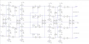
I listened to my prototype for some time and i am very happy with the results. I am now building my final design, but i changed a few things:
- Battery changed to mains power
- Start on audio signal (also for attached power amp)
- baffle step circuit integrated, can be switched on/off with jumper
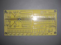
- pcb's from pcb express no veroboard
- optimised circuit
- 1st + 2nd order filter, 2nd order can be switch on/off with jumper
- HP-filter and LP-filter use fixed resistors and variable capacitor for setting frequencies. I do this by adding capacitors from a capacitor bank using jumpers
- same applies for the baffle step circuit. But here i also need a resistor bank. Combinations of capacitor + resistor values give me a my shelving frequency and the amount of "baffle step", depending on the width of the speaker.
- Battery changed to mains power
- Start on audio signal (also for attached power amp)
- baffle step circuit integrated, can be switched on/off with jumper
- pcb's from pcb express no veroboard
- optimised circuit
- 1st + 2nd order filter, 2nd order can be switch on/off with jumper
- HP-filter and LP-filter use fixed resistors and variable capacitor for setting frequencies. I do this by adding capacitors from a capacitor bank using jumpers
- same applies for the baffle step circuit. But here i also need a resistor bank. Combinations of capacitor + resistor values give me a my shelving frequency and the amount of "baffle step", depending on the width of the speaker.
Attachments
- Status
- This old topic is closed. If you want to reopen this topic, contact a moderator using the "Report Post" button.
- Home
- Amplifiers
- Pass Labs
- Two B1 and a crossover