Is that ok? maybe some resistor (1M) have to go!
An externally hosted image should be here but it was not working when we last tested it.
[IMG=http://img175.imageshack.us/img175/9171/graphic1u.th.jpg][/IMG]
Last question
An externally hosted image should be here but it was not working when we last tested it.
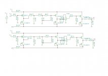
In the highpass R2 comes from R2' and Ramp, so my question is how we calculate the Ramp?
")
Ramp means the input impedance of the following amplifier, you set it to 1M (after the next correction). If you use 10k as R1 (a region which I would recommend, I use it myself) you get R2=10*R1=100k. To get R2' (the only one to solder in, Ramp is only virtual) you calculate
R2' = 1/(1/(10*R1)-1/Ramp) with Ramp=1M
For an R1 of 10k you get 111k, take the nearest standard value and feel glad. This is the only resistor you need here.
Leave out the two R100 (hipass and lowpass), not necessary.
after the next buffer, before the att, leave out the two 1M Resistors to ground, they are not necessary.
I built a stepped att with I think 20k and 6 steps of approx 1dB and set a R of 20k before that att. In closed position the switch will short this R. When the switch is open, the R amd the att will form a voltage divider of 1/2=6dB.
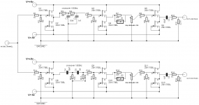
The rest looks o.k. to me. I use a different voltage supply withless capacitance, more regulation. In the first built, I used LM317/LM337 with CRC afterwards. It sounded good enough, so I was lazy and left it in. The C in the CRC is 470uF I think.
The other difference is that I used seperate input buffers for the hipass and the lopass. But if you use R1>=10k, I think you will be on the safe side with one buffer.
Regards

Great, this is what i am looking for. Can i use this circuit for balanced signals? I would like to use 2nd order filtering, so if i am correct i should only use a first order filter for the + and the - branch?
My current passive pre has a 46 step 10K 4 deck volume control, which i would like to use with this. Is that possible? would i have to add 10k to this pot to get the desired 20k?
For a balanced setup i would have to use stereo stepped attenuators for the low and high volume control.
My current passive pre has a 46 step 10K 4 deck volume control, which i would like to use with this. Is that possible? would i have to add 10k to this pot to get the desired 20k?
For a balanced setup i would have to use stereo stepped attenuators for the low and high volume control.
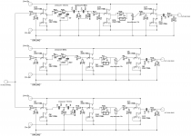
Here is a 3way, for the band pass is better to use one more buffer?
Do it, it would be very hard to match th impedances and an additional B1 (like) does not cost that much and it does not degrade the sound.
I think you need 2nd order for + and for -.Great, this is what i am looking for. Can i use this circuit for balanced signals? I would like to use 2nd order filtering, so if i am correct i should only use a first order filter for the + and the - branch?
I assume you're talking about the volume pot. If your sources can live with the 10k, it's fine.My current passive pre has a 46 step 10K 4 deck volume control, which i would like to use with this. Is that possible? would i have to add 10k to this pot to get the desired 20k?
Yes.For a balanced setup i would have to use stereo stepped attenuators for the low and high volume control.
I think you need 2nd order for + and for -.
Sorry, was thinking too fast. You are right, you get a 6dB slope on + and a 6dB slope on -. The difference of these two is a 12dB slope.
a 6dB/octave slope is effectively half voltage at one octave higher.Sorry, was thinking too fast. You are right, you get a 6dB slope on + and a 6dB slope on -. The difference of these two is a 12dB slope.
Let's put in some numbers.
+2Vpk on the +IN and +1Vpk on the +out
-2Vpk on the -IN and -1Vpk on the -out.
The differential signal at the input is 4Vpk (+2 + |-2| = 4)
The differential signal at the output is 2Vpk (+1 + |-1| = 2)
The output signal is half what the input signal irrespective of whether one measures the +signal alone or the -signal alone or the differential signal.
For 12dB/octave the output voltage would need to be 1/4 (one quarter) of the input at one octave difference. Clearly it is not.
you're original fast thinking answer was correct.you need 2nd order for + and for -
Anybody has a good source for the FET's. I think i need 24 for a balanced setup, so 12 matched pairs.
Another source of matched jfets on link below...
The differential signal at the input is 4Vpk (+2 + |-2| = 4)
The differential signal at the output is 2Vpk (+1 + |-1| = 2)
...
For differential signals (root word: Difference), the above should be +2 - (-2) = +4 and so on...
a 6dB/octave slope is effectively half voltage at one octave higher.
Let's put in some numbers.
+2Vpk on the +IN and +1Vpk on the +out
-2Vpk on the -IN and -1Vpk on the -out.
The differential signal at the input is 4Vpk (+2 + |-2| = 4)
The differential signal at the output is 2Vpk (+1 + |-1| = 2)
The output signal is half what the input signal irrespective of whether one measures the +signal alone or the -signal alone or the differential signal.
For 12dB/octave the output voltage would need to be 1/4 (one quarter) of the input at one octave difference. Clearly it is not.
you're original fast thinking answer was correct.
O.k. thanks for the light Andrew. Sometimes thinking doesn't help... (especially with me).
With best regards
Flo
Anybody has a good source for the FET's. I think i need 24 for a balanced setup, so 12 matched pairs.
I always bought them from Reichelt (in Germany). For the B1 matching isn't as important as when you're dealing with differential pairs (long tailed) and the absolute values (Idss etc.) do not matter. If you buy 30-40 of those little critters and select the closest ones for a pair it should be good enough.
But if you find a good source for matched pairs, go for it.
Regards
If i would use 2nd order filter for 2000Hz and 3000Hz, i could use the same resistors and only change caps right?
Could i also make this switchable to be able to drive the two speakers i have
1) Visaton 170Al with 2000Hz
2) Monitor with 3000Hz
I would use an internal switch for this and keep the lines to the caps short.
Could i also make this switchable to be able to drive the two speakers i have
1) Visaton 170Al with 2000Hz
2) Monitor with 3000Hz
I would use an internal switch for this and keep the lines to the caps short.
Yes, you could even set the caps or the whole filter-network on an ic-socket and make it interchangable. If you place the values you will need on the board, you can use jumpers - I think Passlabs do it like that, DIP-swiches, relays, what ever you like.
Look for the things that are used in phono-preamps to set the input impecance whatever fits there will fit in your crossover too. But I would not recommend anything like switches on the front with long cables. The length of the signal-path is not really critical but you should not exceed some cm.
Look for the things that are used in phono-preamps to set the input impecance whatever fits there will fit in your crossover too. But I would not recommend anything like switches on the front with long cables. The length of the signal-path is not really critical but you should not exceed some cm.
Last edited:
- Status
- This old topic is closed. If you want to reopen this topic, contact a moderator using the "Report Post" button.
- Home
- Amplifiers
- Pass Labs
- Two B1 and a crossover