The 50W halogen bulb will offer little or no protection.
The property we are interested in in a lightbulb or protection purposes is the large increase in resistance that occurs at the nominal operating point. When cold (small signal levels) the resistance is very low, and has no real effect. Under sustained high signal levels the resistance increases and forms a voltage divider with the driver and thus offers protection. The change in resistance is on the order of 20:1, and takes tens of milliseconds to occur. This behavior allows musical transients to pass, but limits sustained overdrive in an intelligent manner (and doesn't sound horrible either).
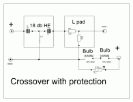
"The lightbulb is situated as the first component in the Hi-Pass filter.
I would think that the position of the bulb before the hi-pass filter is significant."
It is both smart and not-a-good-idea at the same time.
If the crossover is connected directly to the driver it is a good idea in that if the driver or bulb opens it prevents damage to the network (if a network with a higher than 6dB slope loses its load the network drops to zero impedance at its resonant frequency, and either a cap will blow, or the inductor will burn).
If there is a pad between the network an the driver (typical as the horn is likely to be many dB louder than the woofer), the lightbulb cannot work in any sensible fashion, and must handle much more current.
Off-the-shelf networks are seldom useful, I never use them.
"In my experience blown tweeters are usually the result of a clipping amplifier.
The square wave harmonics will quickly overload the HF Driver.
If this is the case here, a signal limiter before the power amplifier will pay for its self. "
This is totally wrong, but since it has been repeated (it seems like forever) it must somehow be true? Please re-read post #50.
The property we are interested in in a lightbulb or protection purposes is the large increase in resistance that occurs at the nominal operating point. When cold (small signal levels) the resistance is very low, and has no real effect. Under sustained high signal levels the resistance increases and forms a voltage divider with the driver and thus offers protection. The change in resistance is on the order of 20:1, and takes tens of milliseconds to occur. This behavior allows musical transients to pass, but limits sustained overdrive in an intelligent manner (and doesn't sound horrible either).
"The lightbulb is situated as the first component in the Hi-Pass filter.
I would think that the position of the bulb before the hi-pass filter is significant."
It is both smart and not-a-good-idea at the same time.
If the crossover is connected directly to the driver it is a good idea in that if the driver or bulb opens it prevents damage to the network (if a network with a higher than 6dB slope loses its load the network drops to zero impedance at its resonant frequency, and either a cap will blow, or the inductor will burn).
If there is a pad between the network an the driver (typical as the horn is likely to be many dB louder than the woofer), the lightbulb cannot work in any sensible fashion, and must handle much more current.
Off-the-shelf networks are seldom useful, I never use them.
"In my experience blown tweeters are usually the result of a clipping amplifier.
The square wave harmonics will quickly overload the HF Driver.
If this is the case here, a signal limiter before the power amplifier will pay for its self. "
This is totally wrong, but since it has been repeated (it seems like forever) it must somehow be true? Please re-read post #50.
Drivers fail for two reasons:
Excess average power
Mechanical damage
Clipping will not hurt anything if it does not cause the above problems.
If there is a pad between the network an the driver (typical as the horn is likely to be many dB louder than the woofer), the lightbulb cannot work in any sensible fashion, and must handle much more current.
When an amplifier clips this causes the output at a given frequency to become a square wave instead of a sine wave. This change in shape of the waveform is gross distortion and consists entirely of harmonics of the fundamental frequency. This increased high frequency component is the screaming tearing sound that comes from a clipping amplifier.
The increased level of high frequency signal causes the HF driver failure.
Clipping an amplifier will also have an effect on the LF driver. By changing the signal to a square wave the power disipated by the driver is increased from the RMS value to the Peak value so by a factor of 1.41
So a 500W amplifier will deliver over 700W power to the driver if clipped hard enough.
As for using a L pad attenuator the idea of this is to maintain the same Resistance - Impedance as the Driver ie 8R0 to allow the crossover components to correctly filter the frequency. So how does this increase the loading?
"As for using a L pad attenuator the idea of this is to maintain the same Resistance - Impedance as the Driver ie 8R0 to allow the crossover components to correctly filter the frequency. So how does this increase the loading? "
Is this a trick question?
It would seem obvious that the size of the lightbulb would need to be changed for every different attenuation value (if it's to be of any use).
"So a 500W amplifier will deliver over 700W power to the driver if clipped hard enough."
Really? Power goes with the square of the voltage, so it goes from 500W to 1KW, but that has little or nothing to do with why the drivers blow.
Clipping can damage speakers, but not for the 'urban legend' reasons.
"If you’re getting the idea I don’t believe in the clipping/
harmonic theory, you’re right. So let’s investigate the
phenomena further.
WHEN SINE WAVES CLIP
When sine waves clip severely they resemble square
waves in shape, introducing massive distortion. In the
extreme case, a perfect square wave has the highest level of
harmonic components (See Figure 1). A less clipped sine
wave has components at the same frequencies but at lower
levels.
Let’s look at the square wave example shown in Table 1
(at left). Fourier analysis shows the harmonic structure.
As you can see, the total amount of instananeous power
left to make it through an ideal 1kHz crossover (and on to the
tweeter) is less than two watts (0.83 + 0.589 = 1.419W).
Hardly a problem. And remember, this simulates severe
overdrive of a 100 watt amplifier with a sine wave to make an
ideal square wave. Driving it harder will not increase the
harmonics.
This analysis shows if a small tweeter that only handles 5
or 10 watts is used in a 100 watt speaker system it would not
blow out, even under square wave conditions. Yet it does.
It takes a lot more than this to cause major failure. "
Consider a worst case situation, an amplifier overdriven by 10dB or so.
The bass content of the program material causes the amp to clip, the excess HF content from clipping harmonics fed to the tweeter is trivial.
However, the average level fed to the speaker at mid and high frequencies is elevated as much as 10dB (due to the input overdrive) during non-clipped passages.
WOOFER MECHANICAL DAMAGE
(assume the design has sufficient x-max for in-band signals)
It's not the clipping per se, but the poor design of the amplifier causing this. The pole in the feedback loop is generally poorly chosen and lower in frequency than the input pole, and above the power supply/load pole, so the poorly designed amplifier pumps out rail-to-rail signals at the feedback pole every power supply time constant. Good design reduces or eliminates this problem (although it seems like 99% of amplifiers have this problem).
The easiest way to fix this is to change the poles so the feedback pole is at a higher frequency than the power supply pole, and the input pole is higher than the feedback pole. It also helps to put clamp diodes across the feedback cap.
Another way to fix this is to put an input clipper on the amplifier. NAD amplifiers have this kind of a circuit (they call it 'soft clipping') and it tracks the supply voltages so you get the maximum power the amplifier is capable of. Since the input clips before the feedback loop clips, it's always stable. I used to put 50W NAD amplifiers in clubs with four Klipsch Heresy on them, you wouldn't believe how loud this combo will play driven a few dB into clipping.
"2) Many crossovers barely handle the rated power of a speaker system, let alone the effect of a clipping amplifier. When inductors saturate, the tweeter gets not only the normal signal at high power, plus the distortion products from the clipping, but also back EMF from the saturating inductors and signals below the normal crossover frequency because the filter system in overload."
Only the cheapest of speakers use low quality parts these days. Back-in-the-day a network needed the tweeter cap replaced (if it was an electrolytic) or the tweeter inductor (if the tweeter cap was a film type) after the tweeter burned out and the operator continued to play the system. In 30 years I can pretty much count on one hand the woofer inductors that failed in hi-fi use, these all developed shorted turns (causing damaging infrasonic woofer excursions). In pro sound I saw quite a few woofer inductors fail from too high of a DC resistance (causing the insulation to burn off the wire and the inductor to short out).
The last KW is the most important, how it behaves at the limit.
A well behaved amplifier with no dynamic off-set when driven 6dB into clipping sounds much better than a wimp amp with a built in limiter, even if it is twice the rated power.
(This is tiresome as I have explained it many times before. The above was a compilation of many old postings of mine, I hope it is intelligible)
Got it djk.
Thanks for ur efforts to explain in details.
The pad is required as u hv stated.
Now u hv also stated that the lightbulb cannot work in any sensible fashion.
The market crossover put the bulb after L pad.
what r ur suggestions?
Thanks for ur efforts to explain in details.
If there is a pad between the network an the driver (typical as the horn is likely to be many dB louder than the woofer), the lightbulb cannot work in any sensible fashion, and must handle much more current.
The pad is required as u hv stated.
Now u hv also stated that the lightbulb cannot work in any sensible fashion.
The market crossover put the bulb after L pad.
what r ur suggestions?
This is what JBL person hv to say regarding light bulb use :
Our car audio crossovers use this same kind of circuit, but instead of a light bulb, we use a resistor to attenuate the tweeter by a specific amount.
The reason to use the bulb is that its resistance depends on temperature rather than strictly on the input current. The time that the current flows through the bulb increases the temperature. That means that huge high-frequency musical peaks don't contribute much to heating the bulb, so transients are, for the most part, unaffected.
If the bulb is placed between the amplifier and the crossover filter, the terminal load of the crossover isn't affected by the increasing resistance of the bulb so the blub doesn't affect the crossover's response. However, placing the bulb there in the circuit means that it'll see low frequency transients as well, which may light the bulb and limit the current to the tweeter unnecessarily. Placing the bulb after the crossover provides the correct frequency response until the bulb lights, but at really high input power, the crossover changes and depending on the circuit, can sound really ugly, even though the tweeter won't blow.
This is why we use the polyswitch and the resistor, placed either before or after the filter, depending on it's effect on the frequency response.
--------------------------------------------------------------------------------
Global Product Line Manager, JBL Car Audio
Harman Consumer
Normally the operator is trying to get maximum output.
The amp will be say 600W~800W for 4 compression drivers.
But the signal is boosted by mixer.
Hence consider more safety.
"
Clipping can damage speakers, but not for the 'urban legend' reasons.
Consider a worst case situation, an amplifier overdriven by 10dB or so.
The bass content of the program material causes the amp to clip, the excess HF content from clipping harmonics fed to the tweeter is trivial.
However, the average level fed to the speaker at mid and high frequencies is elevated as much as 10dB (due to the input overdrive) during non-clipped passages.
WOOFER MECHANICAL DAMAGE
It's not the clipping per se, but the poor design of the amplifier causing this. The pole in the feedback loop is generally poorly chosen and lower in frequency than the input pole, and above the power supply/load pole, so the poorly designed amplifier pumps out rail-to-rail signals at the feedback pole every power supply time constant. Good design reduces or eliminates this problem (although it seems like 99% of amplifiers have this problem).
The easiest way to fix this is to change the poles so the feedback pole is at a higher frequency than the power supply pole, and the input pole is higher than the feedback pole. It also helps to put clamp diodes across the feedback cap.
Another way to fix this is to put an input clipper on the amplifier. NAD amplifiers have this kind of a circuit (they call it 'soft clipping') and it tracks the supply voltages so you get the maximum power the amplifier is capable of. Since the input clips before the feedback loop clips, it's always stable. I used to put 50W NAD amplifiers in clubs with four Klipsch Heresy on them, you wouldn't believe how loud this combo will play driven a few dB into clipping.
The person for whom i am going to make is expert in blowing tweeters. I think that this problem is everywhere. .
So Djk I take on your comments about the amount of distortion caused by clipping an amplifier.
But what is the real world situation here?
Jayam has a 600 to 800w amplifier that is being overdriven buy an inconciderate operator, this is causing HF driver failure.
So what is he to do?
Redesign his amplifier which is obviously one of the 99% of amplifiers that does not clip in a clean and controlled manner?
Sell his 800w amplifier and replace it with a 50W NAD amp?
More than one post in this thread has sugested the use of a limiter, which is common practice in a PA situation.
Any basic compressor limiter used before the amplifier will help in this situation.
One could set the gain to accept a hot signal from the mixer.
Use a gentle compression curve to avoid raising the average program power by too much. But raising the average level so it sounds loud to the insensitive operator.
Set a limit output that will stop the power amp from clipping badly.
Some compressors will even trim the compression dynamically, so if there is excessive limiting the threshold is reduced.
I have had to deal with many DJ's over the years who try to drive systems to ear bleeding levels. I have always found the use of a compressor limiter preferable to distortion. There is no need with modern PA equipment to drive the output to clipping!
difference between halogen & normal bulb.
2 pcs 12V/50w halogen bulbs in series will not work?
IT will become 24V/50W.
Currenet limited to 2.083 amp.
DCR will be 11.52 ohms.
How does a halogen light bulb produce light?
Halogen bulbs are technically incandescent light bulbs - illumination is produced in both when a tungsten filament is heated sufficiently to emit light or "incandescence." The difference between the two is in the composition of the glass envelope and the gas inside the envelope. A standard incandescent bulb has a heat sensitive glass envelope that contains an inert gas mixture, usually nitrogen-argon. When the tungsten filament is heated it evaporates and deposits metal on the cooler glass envelope (this is why incandescent bulbs appear black at the end of life). This process requires incandescent bulb filaments to be heated less than optimally to give the bulb a reasonable life. The lower filament temperature gives incandescent bulbs their typical orange-yellow, warm appearing light.
What is the difference between a halogen and an incandescent light bulb?
Halogen light bulbs utilize a fused quartz envelope ("capsule") allowing for higher temperatures. Inside the quartz envelope is a vapor, originally iodine, now usually bromine. The tungsten filament evaporates as usual but the higher temperatures are sufficient to cause the tungsten to mix with the vapor instead of depositing on the envelope. Some of the evaporated tungsten is re-deposited on the filament. The combination of this "regenerative cycle" and higher filament temperature results in a bulb that has a longer life and slightly higher efficiency than standard incandescent bulbs. The higher temperature filament also produces the "white" light often associated with halogen bulbs.
2 pcs 12V/50w halogen bulbs in series will not work?
IT will become 24V/50W.
Currenet limited to 2.083 amp.
DCR will be 11.52 ohms.
Halogen lamps
A halogen lamp is an incandescent lamp in which a tungsten filament is sealed into a compact transparent envelope filled with an inert gas and a small amount of halogen such as iodine or bromine. The halogen cycle increases the lifetime of the bulb and prevents its darkening by redepositing tungsten from the inside of the bulb back onto the filament. The halogen lamp can operate its filament at a higher temperature than a standard gas filled lamp of similar power without loss of operating life.
Electrical characteristics
Incandescent lamps are nearly pure resistive loads with a power factor of 1. This means the actual power consumed (in watts) and the apparent power (in volt-amperes) are equal. The actual resistance of the filament is temperature-dependent. The cold resistance of tungsten-filament lamps is about 1/15 the hot-filament resistance when the lamp is operating. For example, a 100-watt, 120-volt lamp has a resistance of 144 ohms when lit, but the cold resistance is much lower (about 9.5 ohms) [38][39]. Since incandescent lamps are resistive loads, simple triac dimmers can be used to control brightness. Electrical contacts may carry a "T" rating symbol indicating that they are designed to control circuits with the high inrush current characteristic of tungsten lamps. For a 100-watt, 120 volt general-service lamp, the current stabilizes in about 0.10 seconds, and the lamp reaches 90% of its full brightness after about 0.13 seconds.
The Eminence crossovers that I referred to in my earlier post have a replacement bulb available.
This is known as a Eminence Crossover Fuse.
This is wired in circuit before the high pass 18db filter so disconnects the reactive crossover components if anything blows.
I used one of these myself as a basis for a speaker crossover that I customised to suit my drivers.
All I can say is this protection bulb is very effective!
If I get a chance I will try one on a variable PSU to find its Voltage & Current handling.
Regards")
This is known as a Eminence Crossover Fuse.
This is wired in circuit before the high pass 18db filter so disconnects the reactive crossover components if anything blows.
I used one of these myself as a basis for a speaker crossover that I customised to suit my drivers.
All I can say is this protection bulb is very effective!
If I get a chance I will try one on a variable PSU to find its Voltage & Current handling.
Regards
Attachments
"Our car audio crossovers use this same kind of circuit, but instead of a light bulb, we use a resistor to attenuate the tweeter by a specific amount. "
So when the switch opens it slams the audio level down in a very noticable fashion, no thanks.
"The reason to use the bulb is that its resistance depends on temperature rather than strictly on the input current. The time that the current flows through the bulb increases the temperature. "
Exactly what I said.
"That means that huge high-frequency musical peaks don't contribute much to heating the bulb, so transients are, for the most part, unaffected. "
Exactly what I said.
"If the bulb is placed between the amplifier and the crossover filter, the terminal load of the crossover isn't affected by the increasing resistance of the bulb so the blub doesn't affect the crossover's response."
Not entirely correct. The source impedance affects the frequency response too.
"However, placing the bulb there in the circuit means that it'll see low frequency transients as well, which may light the bulb and limit the current to the tweeter unnecessarily. "
No, it doesn't. Why dont you measure it and prove it to yourself.
"Placing the bulb after the crossover provides the correct frequency response until the bulb lights, but at really high input power, the crossover changes and depending on the circuit, can sound really ugly, even though the tweeter won't blow."
When used in a typical network with 6dB or more of attenuation this is not correct. As a matter of fact, having the source resistance to the network change produces a similar effect . Try it yourself and see.
"This is why we use the polyswitch and the resistor, placed either before or after the filter, depending on it's effect on the frequency response. "
Electrovoice uses their protection element (polyswitch) between the network and the horn, JBL uses their protection element (series connected lightbulbs) between the amplifier input and the high-pass section of the network for the horn.
jayam000 is wanting protection in a bi-amp set-up, so there is no network involved. If you re-read post #50 you will see I suggested series connected #1156 lamps for 16 ohm 4" Nomex coil-former compression drivers with a 1.5A fast-blow fuse in parallel. The same set-up should work for an 8 ohm 2.84" Nomex coil-former compression drivers, but use a 2A fast-blow fuse (because the driver is 8R).
"Redesign his amplifier which is obviously one of the 99% of amplifiers that does not clip in a clean and controlled manner?
Sell his 800w amplifier and replace it with a 50W NAD amp?"
Either a nasty comment or not understanding the different applications involved. This is refering to damage to low-frequency drivers.
Are you being nasty, or obtuse?
"More than one post in this thread has sugested the use of a limiter, which is common practice in a PA situation.
Any basic compressor limiter used before the amplifier will help in this situation."
It will not, as with increased overdrive , while the amplifier does not clip (assuming the limiter is adjusted properly), the average power continues to increase until the point where the compression driver can still fail. Of course, if the limiter has variable release that can be set to several minutes it will prevent an increase in average power (and there are such devices on the market).
"2 pcs 12V/50w halogen bulbs in series will not work?
IT will become 24V/50W.
Currenet limited to 2.083 amp.
DCR will be 11.52 ohms. "
Really?
Try it and see. What you will find is it becomes 24V/100W.
"The cold resistance of tungsten-filament lamps is about 1/15 the hot-filament resistance when the lamp is operating."
Totally dependant on the size and construction of the bulb. For a PAR64 1000, it draws 225A on the first half-cycle (60hz), but only 8.33A hot (a 27:1 ratio).
The lamps I discussed for limiter applications are about 20:1
"If I get a chance I will try one on a variable PSU to find its Voltage & Current handling"
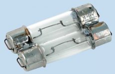
It looks like two 211-2 bulbs soldered together, which means you can make your own for a fraction of the Eminence price.
I encourage everyone to measure for themselves and make their own decisions. I did such over 20 years ago when I took out the bulb from a Boston Acoustics crossover and curved it with a variable DC supply. This bulb had wire leads with '561' stamped in the glass in one end. With metal caps pressed on the ends this bulb is sold as a 211-2. Without the metal caps it is a 561 dome light (used in my Ford E150 van). The wire loops are steel, and as such do not soulder without acid flux. For this reason I use the 211-2. It is easy to solder to, and spring clips that solder to PC boards are available too.
Anyone joining the discussion late is encouraged go back and read post #50.
Sell his 800w amplifier and replace it with a 50W NAD amp?"
Either a nasty comment or not understanding the different applications involved. This is refering to damage to low-frequency drivers.
Are you being nasty, or obtuse?
"More than one post in this thread has sugested the use of a limiter, which is common practice in a PA situation.
Any basic compressor limiter used before the amplifier will help in this situation."
It will not, as with increased overdrive , while the amplifier does not clip (assuming the limiter is adjusted properly), the average power continues to increase until the point where the compression driver can still fail. Of course, if the limiter has variable release that can be set to several minutes it will prevent an increase in average power (and there are such devices on the market).
"2 pcs 12V/50w halogen bulbs in series will not work?
IT will become 24V/50W.
Currenet limited to 2.083 amp.
DCR will be 11.52 ohms. "
Really?
Try it and see. What you will find is it becomes 24V/100W.
"The cold resistance of tungsten-filament lamps is about 1/15 the hot-filament resistance when the lamp is operating."
Totally dependant on the size and construction of the bulb. For a PAR64 1000, it draws 225A on the first half-cycle (60hz), but only 8.33A hot (a 27:1 ratio).
The lamps I discussed for limiter applications are about 20:1
"If I get a chance I will try one on a variable PSU to find its Voltage & Current handling"
It looks like two 211-2 bulbs soldered together, which means you can make your own for a fraction of the Eminence price.
I encourage everyone to measure for themselves and make their own decisions. I did such over 20 years ago when I took out the bulb from a Boston Acoustics crossover and curved it with a variable DC supply. This bulb had wire leads with '561' stamped in the glass in one end. With metal caps pressed on the ends this bulb is sold as a 211-2. Without the metal caps it is a 561 dome light (used in my Ford E150 van). The wire loops are steel, and as such do not soulder without acid flux. For this reason I use the 211-2. It is easy to solder to, and spring clips that solder to PC boards are available too.
Anyone joining the discussion late is encouraged go back and read post #50.
"2 pcs 12V/50w halogen bulbs in series will not work?
IT will become 24V/50W.
Currenet limited to 2.083 amp.
DCR will be 11.52 ohms. "
Really?
Try it and see. What you will find is it becomes 24V/100W.
Yes, u r right djk.
Then how about using 24V/50W bulb if available.
I think it is better to use crossover.
Then i think :
There r two combinations.
1) Resistor parallel to PTC.
2) Bulb parallel to PTC.
Resistor parallel to PTC
As per the Kirchhoff's law, when PTC trips, the resistor & HF will become in series load. Let us select 4 ohm as value for resistor. Then the total resisitance will be 12 ohms. The safe current to HF is 2.236A. Let us assume that this current is flowing through 12 ohm load. 2.236A. Then this combination will be suitable for 60W input power.
HF will get 40 W & additional 20W will be consumed by resistor. So 33.3% power will be consuled by reistor & safety factor increased by 50%. The power reduction will be less than 3 db. Hence noticable to the listner that he is playing overload.
Bulb parallel to PTC
The cold dc resistance is 1/15 as mentioned in the article above for tungstan wire bulb. So when in parallel with PTC it will also consume some current. So it's resistance will increase during normal operation & become little hot. So when PTC trips & full current will flow through bulb, it will become more resistive quickly.
Initially more current will flow through PTC. PTC takes more time to trip. But there is interesting feature about it. More the current, less the time to trip. The PTC are rated for 40A. So no worry of blowing by more current. If we select PTC with low current as required, it will trip in time as suitable for our circuit. I hv attached the PTC specs file.
Attachments
djk
Sorry if misunderstood.
I am going to use passive 18 db crossover.
jayam000 is wanting protection in a bi-amp set-up, so there is no network involved. If you re-read post #50 you will see I suggested series connected #1156 lamps for 16 ohm 4" Nomex coil-former compression drivers with a 1.5A fast-blow fuse in parallel. The same set-up should work for an 8 ohm 2.84" Nomex coil-former compression drivers, but use a 2A fast-blow fuse (because the driver is 8R).
Sorry if misunderstood.
I am going to use passive 18 db crossover.
"Yes, u r right djk.
Then how about using 24V/50W bulb if available. "
That would probably work.
" think it is better to use crossover. Then i think :
There r two combinations.
1) Resistor parallel to PTC.
2) Bulb parallel to PTC."
1) is what EV does,the parallel resistor they typically use is 10R.
2) must have a resistor in series with the bulb, otherwise not enough current will flow through the PTC. I would suggest 2R2~3R3.
A PTC takes a long, long time to trip. Select the value that is 1/3rd the value you calculate. EV uses an RXE050 with the DH3 type drivers (1-1/4" coil), and it will pass 1.5A for 10 seconds before trip (18W/8R). EV uses the RXE075 with the DH2 type drivers (2" coil), and it will pass 2A for 10 seconds before trip (32W/8R). The 10 second trip on the RXE090 is about 2.8A (60W/8R). Be sure and use 60V (or higher) rated PTC parts many are only rated to interupt low voltage, the RayChem RXE seres is 60V.
Keep in mind that the PTC devices have a finite cycle life. The post trip (recovered) resistance gradually increases to the point at which you will want to replace it (causes too much insertion loss or just plain fails).
I seldom use a PTC, I generally just use the bulb (as does JBL on most of their smaller PA models). The older UREI/JBL studio models just used the bulbs. EV used to use the relay method with a bulb, then they went inexpensive with the PTC and a resistor.
Sample schematics:
http://www.jblproservice.com/pdf/JRX Series/JRX125.pdf
http://archives.telex.com/archives/EV/Speakers/Service Manuals/MTH-1 Service.pdf
Last edited:
Learning from djk,
I hv designed protection circuit with 12V 35W/35W bulb.
Calculating when PTC is tripped.
Here the bulb will become 24V 70W.
DC resistance of bulb will be 8.23 ohm.
Current at full 24 volt will be 2.91A.
Assuming the tweeter to be 50W.
Hence at 20V current will be 2.5A.
Voltage drop across bulb when 2.5A pass :
V = RI i.e. 8.23 x 2.5 = 20.57V.
what r ur views about the circuit?
Attachments
or even better
Or an even better protection method :
Learn more about speakers
what is A,B,C order of passive xovers
what is spl
what is sensitivity
what is the lilte tricks required to match a few units in a box
what is the reason speakers often blow ( mainly distrotrionxtime and not powerxtime)
this will result everlasting speakers that also sound perfect
( where i come from there is a louny that creates PA speakers that uses for high frequency tonsil horn tweeters .... nice unit but low construction quality and low power .....he uses more than one some times 3-4 horns per speaker ....so he uses combination of series parallel between tha horns and some sophisticated kind of passive xover ....the speakers are rated 200 w programm 300 max ...and last for ever .... they also sound nice but this is not the point really )
Try an automobile parking light in series with the load.
Or an even better protection method :
Learn more about speakers
what is A,B,C order of passive xovers
what is spl
what is sensitivity
what is the lilte tricks required to match a few units in a box
what is the reason speakers often blow ( mainly distrotrionxtime and not powerxtime)
this will result everlasting speakers that also sound perfect
( where i come from there is a louny that creates PA speakers that uses for high frequency tonsil horn tweeters .... nice unit but low construction quality and low power .....he uses more than one some times 3-4 horns per speaker ....so he uses combination of series parallel between tha horns and some sophisticated kind of passive xover ....the speakers are rated 200 w programm 300 max ...and last for ever .... they also sound nice but this is not the point really )
- Status
- This old topic is closed. If you want to reopen this topic, contact a moderator using the "Report Post" button.
- Home
- Amplifiers
- Solid State
- tweeter ( Compression driver) protection circuit