I modified my arm again based upon Hans’ analysis.
From his analysis, I think my air bearing arm has very good damping laterally because the air bearing is heavy. Therefore, there are very low level of FM. However, my arm has no arm tube. It is basically a head shell attached on air bearing and there is very little damping vertically. This is why FM mostly correlates with vertical movements.
Hans’ analysis reveals the shortcoming which I never realized before for an air bearing arm with very short arm.
In order to add vertical damping, I modified the head shell to redistribute the weight of mass. I made a weight of 11 grams with lead sheet and attached it on the tip of head shell so once the cartridge is thrown up by a warped record, the added weight will effectively force the cartridge down. In the meantime, the weight will keep the stylus in groove better than it without the weight.
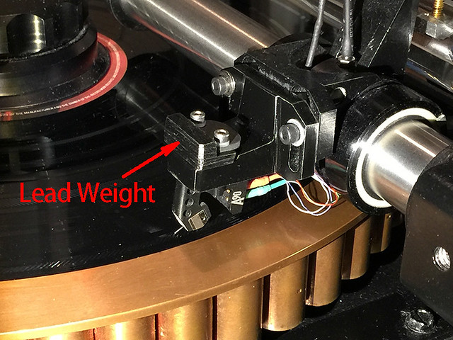
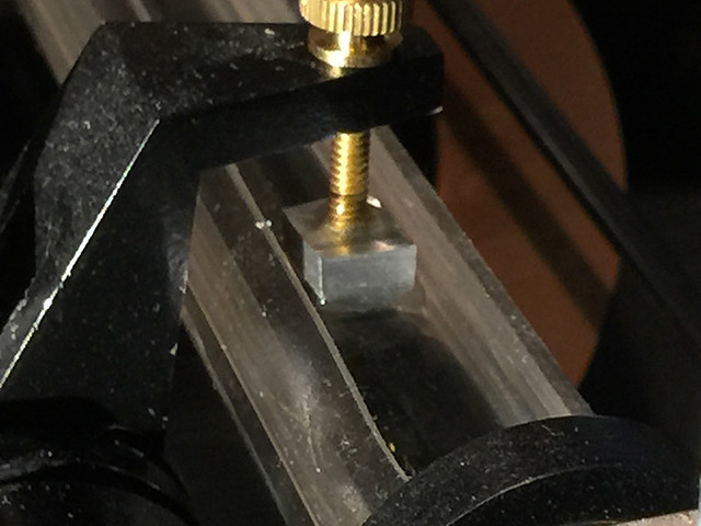
I also engaged vertical damping device. I can also increase the area facing down to increase vertical damping force if necessary.
Here are two new tracks with modification and vertical damping. These are the same tracks from Hi-Fi News Test LP as l did before. The resonance frequencies are changed a little bit due to the change of head shell and cartridge. Both vertical and lateral resonance frequencies are about 5 Hz which are slightly higher than these were before. The cartridge I used was different from last time. I used Denon DL-103R last time. It was Ortofon A-90 this time.
Hans, if you have time, please do the same analysis as last time. I would like to see if there are any changes now. This time I extracted a 8 Hz wav file for vertical module and a 7 Hz wav file for lateral modules.
Dropbox - 7 Hz lateral resonance test.wav
Dropbox - 8 Hz vertical resonance test.wav
From his analysis, I think my air bearing arm has very good damping laterally because the air bearing is heavy. Therefore, there are very low level of FM. However, my arm has no arm tube. It is basically a head shell attached on air bearing and there is very little damping vertically. This is why FM mostly correlates with vertical movements.
Hans’ analysis reveals the shortcoming which I never realized before for an air bearing arm with very short arm.
In order to add vertical damping, I modified the head shell to redistribute the weight of mass. I made a weight of 11 grams with lead sheet and attached it on the tip of head shell so once the cartridge is thrown up by a warped record, the added weight will effectively force the cartridge down. In the meantime, the weight will keep the stylus in groove better than it without the weight.
I also engaged vertical damping device. I can also increase the area facing down to increase vertical damping force if necessary.
Here are two new tracks with modification and vertical damping. These are the same tracks from Hi-Fi News Test LP as l did before. The resonance frequencies are changed a little bit due to the change of head shell and cartridge. Both vertical and lateral resonance frequencies are about 5 Hz which are slightly higher than these were before. The cartridge I used was different from last time. I used Denon DL-103R last time. It was Ortofon A-90 this time.
Hans, if you have time, please do the same analysis as last time. I would like to see if there are any changes now. This time I extracted a 8 Hz wav file for vertical module and a 7 Hz wav file for lateral modules.
Dropbox - 7 Hz lateral resonance test.wav
Dropbox - 8 Hz vertical resonance test.wav
Last edited:
Hi Jim,
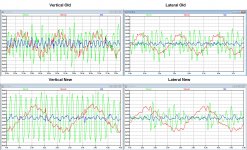
You can see a large difference with the previous recording, although recording time was too short this time to find Fres.
For that reason I have picked from all 4 recordings a time piece corresponding to two LP revolutions to make things easier to compare.
In all timegraphs, you see the vertical movement V(vert) in green and the demodulated signal V(mod) in red.
Since the LP is quite eccentric, I have filtered V(mod) below 2Hz, to show the frequency part of the modulated signal that really matters.
This is visible as V(l) in blue.
In my computer model, 1mV corresponds to 0.1% FM modulation.
In the old situation V(l) has visibly a very high correlation to V(vert), the vertical time signal as coming from the Cart.
In the new situation V(l) is much smaller with a much smaller correlation to V(vert).
Also notice that the signal V(vert) itself has a much more stable amplitude in the new situation.
In the Lateral versions, you see in both versions, old and new, that the amplitude of V(vert)is very much driven by the LP’s eccentricity, with a cycle time of 1.8 sec.
V(l) in the new situation seems a bit smoother with a tad more FM modulation.
All in all, this is a clear improvement.
Hans
Attachments
Hans,
Thanks for your wonderful work!
I also noticed that the patterns of V(mod) and V(I) in vertical movement are very similar to the patterns of V(mod) and V(I) in lateral movements. I am not sure what it tells me.
I have another question for you. Pardon me if the question doesn’t make sense.
All the analysis you did were in low frequency areas. These low frequencies are way under 20 Hz. Does it make more sense to do some analysis within audible range of 20-20 kHz?
Jim
Jim,
I would suggest you to remove the lead and let the damping as it is now.
More weight means a lower Fres, which is not the right direction.
The higher Fres the better.
Hans
Hans,
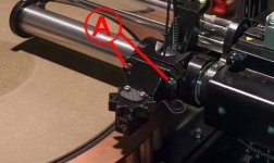
Please see attached photo. This was old head shell. My modification was to remove some part of the head shell and added weight in front of the head shell. So, total mass doesn’t change too much, but its distribution was changed. I can take the weight off, but at this point, I still believe it works in certain degree. In addition to that, if I take away the weight, the resonance frequencies may fall into 7 Hz, which is warp frequency. Although I have a heavy outer ring, I want to try to avoid it. However, I may try to take the weight away to see how much the resonance frequencies will be changed.
Jim
Attachments
Last edited:
To my feeling this means that damping is quite in balance for horizontal and vertical movements.Hans,
I also noticed that the patterns of V(mod) and V(I) in vertical movement are very similar to the patterns of V(mod) and V(I) in lateral movements. I am not sure what it tells me.
Absolutely, that's what the Test LP thread is all about.All the analysis you did were in low frequency areas. These low frequencies are way under 20 Hz. Does it make more sense to do some analysis within audible range of 20-20 kHz?
Jim
But in the meantime you could make a recording of a silent track.
The noise spectrum may well show the (Vertical) Cart resonance.
Another option would be to play a 3150Hz or a 1 Khz tone, recorded somewhere at -20 dB.
The FM modulation resulting in IM distortion caused by Fres will become evident,
Even more severe is to have a combination of 3150Hz plus 315Hz or whatever combination.
When in a bit of a hurry you could use the Adjust+ LP for all this, or you can wait until the DiyAudio Test LP is ready. The latter will give you even more options for testing.
Hans
But in the meantime you could make a recording of a silent track.
The noise spectrum may well show the (Vertical) Cart resonance.
Yes, a recording from a lead-in or a lead-out grove will do. Run an FFT on it.
Even a recording from a music track will do.
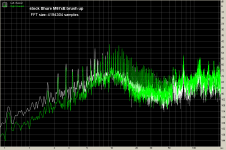
Here is a 1 minute sample from “O fortuna” (track 1 Side 1 Carmina Burana, Carl Orf)
(Shure M97, SME 3009 Improved, ThorensTD160, Hagerman Bugle RIAA pre)
Vinyl track, Shure M97 stock
Vinyl track Shure M97 stylus assy glued to the body.
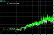
CD track for comparison
George
Attachments
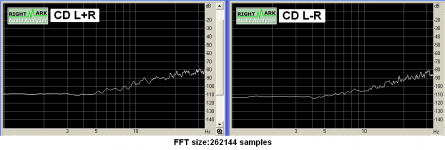
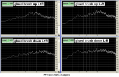
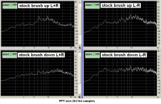
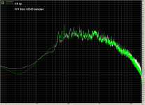
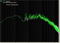
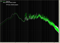

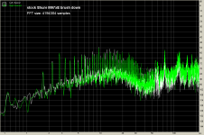
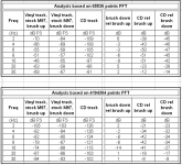
Very informative to see the noise spectrum around Fres coming down some 5 to 10 dB with brush applied.
I made a small table for easy comparison, see attachment1.
Upper table is based on 65536 points FFT
Lower table is based on 4194304 points FFT
We have to remember that low resolution FFT level skirt incorporates the peaks due to record eccentricity, while with higher resolution FFT we are able to estimate the base frequency level, separating it from the 0.55Hz effect.
I didn’t want to scare you much.Nice graphics

Increasing the FFT samples, the ugly eccentricity peak consequences show up, see attached screenshots.
George
Attachments
Hi Hans
I can’t say if the idea has been abandoned.
Is the patent still in force? (US4275888 Jun30, 1981)
IMO the Shure brush as implemented in M97xE is doing a multitude of good things. Damper for arm/cart resonance and disk warp up-down motion, vinyl surface static electricity conduit preventing discharge spikes generation, dirt brushing away from the tip (plus needle tip protection from mishandling)
Some say the brush smears the sound.
I can’t hear any audible degradation. Here is the 1 minute extracts from the track "O fortuna", you may be able to hear what I don’t.
1 stock-brush up trimmed.wav
Dropbox - 1 stock-brush up trimmed.wav
2 stock-brush down trimmed.wav
Dropbox - 2 stock-brush down trimmed.wav
3 glued-brush up trimmed.wav
Dropbox - 3 glued-brush up trimmed.wav
4 glued-brush down trimmed.wav
Dropbox - 4 glued-brush down trimmed.wav
5 cd trimmed-5dB.wav
Dropbox - 5 cd trimmed-5dB.wav
The tracking weight tonearm setting has to be increased by ½ gram for to balance the reaction of the brush. (e.g set for 2.0 gram for an effective VTF of 1.5gr at the needle tip when brush is engaged)
George
George,
I didn't expect to hear any difference at all, but I did.
I listened to 1,2 and 5 through Jriver, all three passages carefully set to exactly the same volume.
Brush up number 1 was the most airy with the best articulation of voices in the low volume passage.
The CD was warmer, had better low, but lacked the spacious sound of 1.
Hans
It was to be expected
One more valid observation supporting the suggestion that vinyl artifacts make for an overall euphonious effect. (I have admitted to it many years ago)
The “brush is smearing the sound” claim that I referred to is based on the scenario that the individual fibers vibrate by following the modulation of the groves, transferring these vibrations to the cartridge.
As they are many and at different groves at the same time, the vibration they transmit is not coherent so they make a soup of sounds.
I admit it is a logical scenario and the possible practical effect is left to the details of the implementation of the brush assy.
IMO, if you want to test of such an effect, you would have to first compare the stock M97 files against the glued M97 files and then the glued M97 up against the glued M97 down file
George
Hi Hans
I can’t say if the idea has been abandoned.
Is the patent still in force? (US4275888 Jun30, 1981)
No.
Hi all,
This really is the most fascinating thread. In my work designing tonearms I have mainly looked at the movement of the cartridge relative to the groove purely as displacement. Although I was aware of the effect that these displacements had in the time domain I hadn't explored this approach as fully as maybe I should. My thinking was, reduce the amplitude of the displacement and all the timing and other nasties go away.
I've held the theory that compliance/effective mass resonance is much more significant in the vertical plane than the lateral for a long time. It's great to see actually measurements that confirm this. Detractors of linear tracking arms often state that their high lateral mass causes "the tail to wag the dog". This is a myth and this thread should help to dispel it. The compliance resonance of a conventional pivoted arm in the vertical plane is much greater than a typical linear tracking arm in the lateral plane. This is partially because warp occur at higher frequencies than eccentricity. But even if you have a perfectly flat record the resonance in the vertical plane will still be dominant. This is despite the fact that the lowest frequency groove modulation is entirely lateral. This may seem counterintuitive. But try dragging a stick across rough ground, the stick will want to bounce up an down much more than it does sideways.
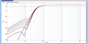
Increasing the frequency at which this resonance occurs so that it falls much higher in frequency than that due to warps, 0.55-~6hz, may seem like a good idea but it can have negative effects. At low audio frequencies the motion of the cartridge is predominantly controlled by the mass of the arm. A higher mass allows the cartridge to move less, try shaking a heavy weight and a light one. I've recycled the graph from a post I made in another thread as it illustrates the point. This graph was made to describe one of Jim's earlier linear tracking arms. The graph shows how much the cartridge body will move relative to the motion of the stylus measured in dB. For an arm/cartridge combo tuned to 10hz the motion of the cartridge body is only 10dB down at 50hz. Increasing the mass so that the resonance is 3.5hz (lower than I would personally go laterally) improves things by 9dB, ie the cartridge body will move by just over a tenth for the same stylus movement. Generally 4 times the mass will halve the resonant frequency and reduce the cartridge movement by 6dB. Within the range that vertical effective mass/compliance would normally be turned to, 8-15hz, the effect is less dramatic, varying by about 2.7dB. As the motion of the cartridge body is about 180° out of phase with the motion of the stylus for most of the audio range the effects are less detrimental than if the phase angle was not aligned thus.
In my opinion the key to controlling the compliance/mass resonance is the application of damping. At the frequencies at which this resonance occurs the armtube is effectively a rigid beam. so where the damping is applied doesn't really matter, a little bit out near the cartridge (Townsend trough, Shure brush) or more near the bearing. Of course the use of a warp flattening clamp will reduce the main force driving the vertical resonance.
My arm is a linear tracker with a total lateral mass approximately 3.5 times its vertical effective mass. Even with this difference in the masses I've still set damping in the vertical plane to be 3 times as great as that in the lateral plane.

Niffy
This really is the most fascinating thread. In my work designing tonearms I have mainly looked at the movement of the cartridge relative to the groove purely as displacement. Although I was aware of the effect that these displacements had in the time domain I hadn't explored this approach as fully as maybe I should. My thinking was, reduce the amplitude of the displacement and all the timing and other nasties go away.
I've held the theory that compliance/effective mass resonance is much more significant in the vertical plane than the lateral for a long time. It's great to see actually measurements that confirm this. Detractors of linear tracking arms often state that their high lateral mass causes "the tail to wag the dog". This is a myth and this thread should help to dispel it. The compliance resonance of a conventional pivoted arm in the vertical plane is much greater than a typical linear tracking arm in the lateral plane. This is partially because warp occur at higher frequencies than eccentricity. But even if you have a perfectly flat record the resonance in the vertical plane will still be dominant. This is despite the fact that the lowest frequency groove modulation is entirely lateral. This may seem counterintuitive. But try dragging a stick across rough ground, the stick will want to bounce up an down much more than it does sideways.
Increasing the frequency at which this resonance occurs so that it falls much higher in frequency than that due to warps, 0.55-~6hz, may seem like a good idea but it can have negative effects. At low audio frequencies the motion of the cartridge is predominantly controlled by the mass of the arm. A higher mass allows the cartridge to move less, try shaking a heavy weight and a light one. I've recycled the graph from a post I made in another thread as it illustrates the point. This graph was made to describe one of Jim's earlier linear tracking arms. The graph shows how much the cartridge body will move relative to the motion of the stylus measured in dB. For an arm/cartridge combo tuned to 10hz the motion of the cartridge body is only 10dB down at 50hz. Increasing the mass so that the resonance is 3.5hz (lower than I would personally go laterally) improves things by 9dB, ie the cartridge body will move by just over a tenth for the same stylus movement. Generally 4 times the mass will halve the resonant frequency and reduce the cartridge movement by 6dB. Within the range that vertical effective mass/compliance would normally be turned to, 8-15hz, the effect is less dramatic, varying by about 2.7dB. As the motion of the cartridge body is about 180° out of phase with the motion of the stylus for most of the audio range the effects are less detrimental than if the phase angle was not aligned thus.
In my opinion the key to controlling the compliance/mass resonance is the application of damping. At the frequencies at which this resonance occurs the armtube is effectively a rigid beam. so where the damping is applied doesn't really matter, a little bit out near the cartridge (Townsend trough, Shure brush) or more near the bearing. Of course the use of a warp flattening clamp will reduce the main force driving the vertical resonance.
My arm is a linear tracker with a total lateral mass approximately 3.5 times its vertical effective mass. Even with this difference in the masses I've still set damping in the vertical plane to be 3 times as great as that in the lateral plane.
Niffy
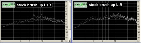
This is one of those off but on topic questions, but as the plots are here seemed the best place to put it. As part of the planning for the integration of my various phono projects I had a re-mull over HPF and noticed that Self has produced PCBs for his 'deviynliser'. In effect this is very similar to a mastering elliptic filter in that it gives very steep roll off for side information and leaves mid untouched. Now although the damage has already been done, and damping is the best way in a undamped system there is still considerable energy in the subsonic region that flaps woofers and eats up ADC headroom so I think its worth the experimentation to see if it's a useful thing to be able to patch in?
Sadly this now means I need 3 inserts in my analog front end. Four if I get the coils on one of my cartridges rotated 45 degrees to give M-S output rather than L-R
Sadly this now means I need 3 inserts in my analog front end. Four if I get the coils on one of my cartridges rotated 45 degrees to give M-S output rather than L-R
Attachments
Hi Niffy,
I'm a bit confused by your graph. The Am/Cart resonance is a second order system.
A second order system, whatever the damping or the Q is, drops down after some time with 40dB/decade.
Yet in your graph between 100Hz and 1000Hz it is only 10dB.
Could it be the scale is wrong ?
Hans
I'm a bit confused by your graph. The Am/Cart resonance is a second order system.
A second order system, whatever the damping or the Q is, drops down after some time with 40dB/decade.
Yet in your graph between 100Hz and 1000Hz it is only 10dB.
Could it be the scale is wrong ?
Hans
- Status
- This old topic is closed. If you want to reopen this topic, contact a moderator using the "Report Post" button.
- Home
- Source & Line
- Analogue Source
- Turntable speed stabilty