My current amp has a NE5534 front end into a 46 driving a 300b. I'm very happy with it. No feedback loop, however, but I thought I'd mention it for the sake of the op-amp/tube combination. The op-amp stage is x5.5 gain. This enables me to use two DHTs that I really love, without compromising with the usual 2 stage high mu IDHT for a 300b driver.
You are running the opamp with no feedback?No feedback loop
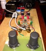
They are open , signal is g1, anode is g2 and 6v6 anode connected to its cathode.
This allows less cutoff g1 voltage.
The idea is to use 6v6 as shield. CCS is 700ua. Signalwise all is good.
Just a low level 60cps.
How about a smaller pentode like a 6au6, using the same logic, G2 as anode and anode as shield, a smaller pentode will certainly generate/pick lower hum cause lower filament current and smaller overall profile, Im currently doing experiments with tubes operating in a similar way for low gain linestage duty, but without opamps in the chain.

Have yet to listen a 6ba6 as triode in that fashion
How about a smaller pentode like a 6au6, using the same logic, G2 as anode and anode as shield, a smaller pentode will certainly generate/pick lower hum cause lower filament current and smaller overall profile, Im currently doing experiments with tubes operating in a similar way for low gain linestage duty, but without opamps in the chain.
Have yet to listen a 6ba6 as triode in that fashion
I did several examples without opamps , they work great but need manual bias/centering which is ok. I did it now with opamp needing no adjust. The opamp is basically just a servo.
This one is line level with first stage headroom 8+ vrms.
Got some metal receiving tubes in to try.
I would say they are more 'articulate' using audiophile jargon.
The gain stage on output has a OPA1622 headphone opamp.
It does well as line amp too.
So headphone or line.
Don't want to say which metal tube because right now plenty out-there.
Output has a 330uf muse bp because of dc offset. Too much for the headphones.
If using as line only then jfet opamp would remove the output coupling caps.
Attachments
Hang on a second…
Doesn't the first op-amp's negative feedback almost completely linearize the output, removing the “tubiness” of the valves?
After all, that's the whole point of an op-amp's huge gain. Typically well over 100,000× and often 500,000× to 1,000,000×. Its “job” is to reduce the signal-amplification path nonlinearity by the same factor as open-loop gain.
Just saying,
GoatGuy ✓
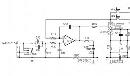
looking at schematic, the first stage output is a mirror of the tubes characteristic. each tube has its own fft spectra.
imo the ideal thd is around 0.2% for music. 60-70db range practicably inaudible but the sound is impressive and very natural sounding.
i use flac but life is injected into mp3 too.
we are 'stealing' the tubes work function profile.
the opamp is maintaining optimum bias point and providing a buffer out to tone-volume controls.
Attachments
Sort of an update, been doing subjective testing and find myself consistently returning to the tube in feedback. In fact I do not like listening to music without the ckt.
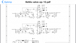
Here is a more complete schematic.
A better way of describing the circuit would be to say the linearized signal is discarded and the tube error signal is output.
Opamp dc output is bias at cutoff depending on current range.
Its usually in the -0.5 to -2.0 volt range. Minus 1 volt being average for various tubes. Grid never goes positive.
Current range is 300uA , 700uA and 1mA by using both CC.
Subjective testing is using 12BH7 which I find has excellent sound quality.
Attachments
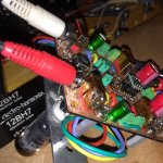
Since the circuit outputs only the error signal it can be used as a sort of fft tube tester.
I ordered a Cryoset EH 12BH7 and will compare the non-cryo to cryo here.
I use a motu M4 front end with two different software analyzers.
I'm aware of all the controversy etc but want to see the fft for myself.
I ordered a Cryoset EH 12BH7 and will compare the non-cryo to cryo here.
I use a motu M4 front end with two different software analyzers.
I'm aware of all the controversy etc but want to see the fft for myself.
Attachments
Test results
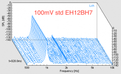
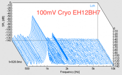
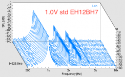
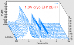
Here are the plots of non-cryo vs cryo EH12BH7.
The voltages were actual measured , one volt and 100 millivolt inputs. Ignore spl scale.
No third/fourth is seen on cryo but thd is higher.
Now I will listen a few weeks for subjective testing.
Here are the plots of non-cryo vs cryo EH12BH7.
The voltages were actual measured , one volt and 100 millivolt inputs. Ignore spl scale.
No third/fourth is seen on cryo but thd is higher.
Now I will listen a few weeks for subjective testing.
Attachments
Last edited:
- Status
- This old topic is closed. If you want to reopen this topic, contact a moderator using the "Report Post" button.
- Home
- Amplifiers
- Tubes / Valves
- Tubes in an opamp feedback loop?