Hang on a second…
Doesn't the first op-amp's negative feedback almost completely linearize the output, removing the “tubiness” of the valves?
After all, that's the whole point of an op-amp's huge gain. Typically well over 100,000× and often 500,000× to 1,000,000×. Its “job” is to reduce the signal-amplification path nonlinearity by the same factor as open-loop gain.
Just saying,
GoatGuy ✓
Sand + glass.
both of which are made from silicon.
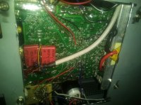
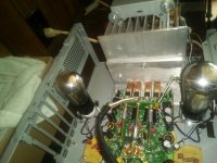
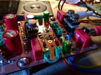
Anyway, in the VAS modified version of my SS stereo proto, this is the way I used glass for VAS, and surprisingly it seems to work marvellously.
This was just for fun, and to see if it actually would work. I do plan to develop the SS version.
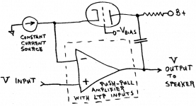
The input here is the current signal output from a THAT2162 voltage controlled amplifier IC, used for volume control. That signal is summed with the DC servo output, translated to voltage signal, and level shifted with a Av of 10 relative to the -140V regulated rail. Like a giant hollow J-fet, the triode is bias to the 2.5mA CCS plate load to balance 0V DC on the output. +/-30Vp on plate, +/-4Vp on grid so less than 1V total op amp swing. The gain is needed because of the low u of this particular triode, but linearity is gained by operation in the sweet spot. There is a loop around the triode but feedback factor is low, and the loop does not contain the op amp (DC servo doesn't really count). I plan to experiment with this some, and the compensation. Always a trade off with that. And microphonics, placing the enclosure onto cloth and rubber grommets for the sockets helps greatly with that. I may try a similar scheme with 12AX7, but as CG instead of CC amplifier. Besides, experimenting is the fun part. For what good these old tubes may have in linearity, they loose in Gm, according to the datasheets the UX201A is even less than 12AX7, less than 800 umhos!. Fortunately the input Z of the crazy output follower stage happens to be very high.
both of which are made from silicon.
Anyway, in the VAS modified version of my SS stereo proto, this is the way I used glass for VAS, and surprisingly it seems to work marvellously.
This was just for fun, and to see if it actually would work. I do plan to develop the SS version.
The input here is the current signal output from a THAT2162 voltage controlled amplifier IC, used for volume control. That signal is summed with the DC servo output, translated to voltage signal, and level shifted with a Av of 10 relative to the -140V regulated rail. Like a giant hollow J-fet, the triode is bias to the 2.5mA CCS plate load to balance 0V DC on the output. +/-30Vp on plate, +/-4Vp on grid so less than 1V total op amp swing. The gain is needed because of the low u of this particular triode, but linearity is gained by operation in the sweet spot.
There is a loop around the triode but feedback factor is low, and the loop does not contain the op amp (DC servo doesn't really count). I plan to experiment with this some, and the compensation. Always a trade off with that. And microphonics, placing the enclosure onto cloth and rubber grommets for the sockets helps greatly with that. I may try a similar scheme with 12AX7, but as CG instead of CC amplifier. Besides, experimenting is the fun part. For what good these old tubes may have in linearity, they loose in Gm, according to the datasheets the UX201A is even less than 12AX7, less than 800 umhos!. Fortunately the input Z of the crazy output follower stage happens to be very high.Attachments
Last edited:
Member
Joined 2006
What about a VFET in a power opamp loop?
Its called supertriode configuration by the late Kamijo san.
Amplified triode
And some other supertriode circuits by tubecad here:
More Super-Triode Ideas
Its called supertriode configuration by the late Kamijo san.
Amplified triode
And some other supertriode circuits by tubecad here:
More Super-Triode Ideas
Attachments
A vacuum tube in an NFB loop will give you the *opposite* result of what you are seeking, since the Op Amp will try HARD to compensate for it, so if you want to add "tubyness" it´s not the way.
I first found that, repairing Guitar oriented Ada Microtube Guitar amplifiers: basically a normal SS power amp (there were Bipolar versions, this one, and ADA Micro Fet , with MosFet outputs) which included a 12AX7 half inside the loop.
I was baffled because when I found the output clipped like a regular SS amp, flat top and all, I scoped tube plate to find what it was actually contributing and to my amazement found a "tit" or "nipple" shaped waveform instead of the smoothly rounded one I expected. WTF?
Until I realized that NFB tried to compensate for power transistor nonlinearity (which was starting to clip) and applied exact opposite error correcting signal.
Basic NFB behaviour.
IF you want tubyness, best is to use tube "raw", no correction applied, so you let it display all its glorious "flaws" ... and then faithfully amplify that.
Yes, and that's exactly what the opamp (it's a LF351 in the original circuit) does in the headphone amp shown in #1. This amp provides tons of output power into the headphone, but no more tubyness at all.
Best regards!
Attachments
This is what Ampeg does to preserve "Tubyness" as much as they can, but mainly to transfer "tube clipping" straight to speakers: they make a full tube gain stage and then drive a Mosfet pack which provides just current gain so it can drive a speaker, but in theory "adds nothing on its own"
Unity voltage gain, faithfully follows tube signal (until it clips on its own that is) , main point: NO NFB , specially nothing feeds back into the tube section.
All they use is a Servo to keep offset manageable, but it´s completely removed from Audio signals.
So in a nutshell: let Tube do its thing, just accurately reproduce that, add no "correction" of any kind.
Attachments
This is what Ampeg does to preserve "Tubyness" as much as they can, but mainly to transfer "tube clipping" straight to speakers: they make a full tube gain stage and then drive a MOSFET pack which provides just current gain so it can drive a speaker, but in theory "adds nothing on its own" … So in a nutshell: let Tube do its thing, just accurately reproduce that, add no "correction" of any kind.
Nice tube-y front end. a tad overkill in the voltage follower section following the first transconductance-curve shaping triode (12AX7a), but hey… overkill with the active clamp load of the 4th triode section is sweet. Very nice, actually. Unusual design, rarely seen here at DIY-tube-audio.
I see also that the parallel MOSFET array, the current-drive, is quite robust in the protection-against-output shorts and other thermal run-away possibilities. Seems able to drive a 2-Ω nominal load … or even lower. Cool. Nice soft-cutoff from the 12AX7a and line of cathode followers therein.
Just saying,
GoatGuy ✓
This experiment using tubes in low voltage op-amp circuits has spawned enough line items to fill all of next year 2020.
-triodes and pentodes in output path , conventional fb
-triodes and pentodes directly in fb
-asymmetrical resistor in feedback (tested resistor today)
I use 47k grid stop resistors so grid current is usually very low.
I like having the opamp servo for offset control plus the low distortion in hi-fi tube use.
How about avoiding the silicon and building tube type op-amps to drive the output tubes? This has been done, anf the Philbrick company's were one of the best, at the pinnacle so to speak. The only slightly tricky part is that the neon lamps used as biasing elements in some of them were coated with radium paint (not for the glow) to excite the neon lamps and make them operate more reliably. Zener diodes could be used today or a small lamp, whatever. Light as we know makes the neon lamps ignite better. There is no sin in using solid state parts as power supply type devices.
A recent chapter on op-amps has many quite old references on tube op-amp stuff.
https://www.analog.com/media/en/training-seminars/design-handbooks/Op-Amp-Applications/SectionH.pdf
Many analog computers relied on vacuum-tube op-amps, available commercially from George A. Philbrick's company in 1952. Your audio gear is an analog computer is it not!
Here is the best source of all the data on the GAP/R op amps by George A Philbrick Researches. These have plenty of bandwidth and were used in high stability equipment. They require regulated voltages, but who cares? It's tube op-amps.
The Philbrick Archive
Full specs and srticles and the rest is available there.
I drew a few for my own study in LTspice from the above web site. No simulations due to not using models. The 'speech driver' schematic is a ham radio project idea for a high power modulator.
Just saying, why not consider a tube op-amp?
Attachments
Yes looked at Philbrick and very familiar with them. EPO Houston on Fondren had bins of them, even saw a few recently. I love tube devices- having three ST70 , Univalve and some tube preamps. They sound fantastic.
But I'm looking at tubes for the classroom and home use. Philbrick uses +-300v for a potential of 600vdc on one assembly.
So that is why I'm trying so much to make it work on +-15v 30v potential.
But I'm looking at tubes for the classroom and home use. Philbrick uses +-300v for a potential of 600vdc on one assembly.
So that is why I'm trying so much to make it work on +-15v 30v potential.
Its called supertriode configuration by the late Kamijo san.
Amplified triode
SuperTriode is always intriguing, but is it much better than simple triode + follower?
Here is one model bimo did. I think only difference is GG. It matched real circuit. DOA - Discrete Op Amps
I had a few minutes and did quick check. It did make a 'tit' when tube in fb as shown. Have to overdrive but it there. So I'm not looking at that topology as far as fb spot.
I had a few minutes and did quick check. It did make a 'tit' when tube in fb as shown. Have to overdrive but it there. So I'm not looking at that topology as far as fb spot.
Attachments
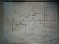
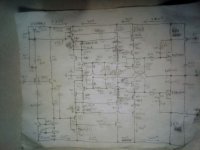
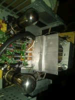
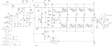
During the lockdown I did an improved stereo super triode.
Shown here 1st article using Crosley/Ken-Rad 6K6G pentodes in G2Anode triode mode.
It drives both line level and headphones.
The tube rolling aspect is interesting.
Tubes with same designation exhibit vastly different FFT spectra.
There is provision for output coupling capacitor but have not needed it so far.
The circuit is somewhat unusual, can you spot it?
Hint: Remember its a tube in feedback loop.
Schematic attached.
Attachments
- Status
- This old topic is closed. If you want to reopen this topic, contact a moderator using the "Report Post" button.
- Home
- Amplifiers
- Tubes / Valves
- Tubes in an opamp feedback loop?