I'll indeed check carefully stock levels before confirming any orders.
And i'll need to include input sockets, speakers output connections, mains input socket......
I've printed the list but i feel i need to add some columns to include these suppliers:-
https://www.rapidonline.com/
https://www.digikey.co.uk/
https://www.mouser.co.uk/
I'm a bit lost on the case to use as I would really prefer to have the valves and transformers mounted on top of the case (classic amps).
I've ordered (shipped already) from Tubelabs (George) the PCB's.
Get some paper- cut out some sizes and see how they fit. Stephe makes it look easy as she has experience in it.
You want space between AC, rectification and any power supply output. A good couple of inches between any AC power side and the clean DC/signal wiring.
A power coated steel case with a base plate will give you RF shielding but if the AC wires are not dressed then that's a mute point. An IEC mains common mode filter will help reduce AC some noise before it even gets into the closed box. I went for a large hammond case initially - simply because it's my "lab" case so has more holes and sockets than I need to test a number of ideas. What you do want is a hole punch to cut the tube holes.
I assume you've not got a current limiter, isolation transformer or variac?
Solder, flux, desolder sucker/braid. An entire thread war could be had by what choice you'd make for those! A solder flux pen is great to get the solder to flow nicely.
You'll want some insulating standoffs for the PCB mounting in the case.
Creating the BOM for the first time is quite an overload of information.
Due to the complexity I used mouser's projects, created chunks of the BOM in separate projects. Delete from the basket and then you have the template project for later.
Once ready and you've triple checked, you can then order each project and it will collate the components together. Probably not needed for this build due to the known list etc.
As always - you can spend an arm and a leg on the components but check through the components you've selected in passes:
a) is the voltage rating correct? (resistor voltage rating, capacitors etc - that includes DC and AC ratings)
b) is the wattage rating correct? (resistor wattage rating)
c) is the current rating correct? (main caps - a tube amp less of an issue)
d) is the type of component correct? (metal foil, wire wound, axial and though hole etc)
e) is the tolerance for the component correct? (% for resistors etc)
f) is the number of each component correct in the BOM
The majority of those will be in the BOM from tubecad. Everyone has their favourite brand and model of component.. for your first tube amp as long as it doesn't blow up and does the job then it's all good - you can change bits at a later date with experience.
I always select "in stock" and "no additional charge". Some components have a one off £15 additional charge for shipping from the states. Filtering that out is easier on the wallet. I usually take known brands rather than suspect Chinese brands and select models that focus on low noise for resistors etc (yes I'm a Vishay Dale resistor tart with MRF, CPF and RN65, YAEGO for the power in the current build and my caps are WIMA MKP4, FKP1, Nichicon and CDE). You don't need to follow that as mouser has a good reputation so whatever is going to be decent.
Just take the BOM that tubecad gives - add a column for each check and a column for the selected URL. I browse through and put in the parts urls, then tick off the checks for the URL then go through the process of ordering parts.
As you get more experience it will become easier but having a plan will stop you from accidentally ordering the wrong components.
Last edited:
I noted the tube cad BOM doesn't state a output transformer - so I would find this first. I would also focus on the this for the budget.
You could contact primary windings and send them the URL link to the output transformer required. They can then point you in the right direction of the transformer (7 pages and no search by impedance).
You will need to know which tubes you're going to use - the output transformer needs to work with the output tube(s). They can then offer power and choke too - no harm asking if they'd offer a discount")
Unfortunately ironwork costs. It's a fact and you'll have to live with it sucking up your budget. Also as tubelab point out - it's not a component you're likely to change. (OTL isn't cheaper than OPT'd amps)
You could contact primary windings and send them the URL link to the output transformer required. They can then point you in the right direction of the transformer (7 pages and no search by impedance).
You will need to know which tubes you're going to use - the output transformer needs to work with the output tube(s). They can then offer power and choke too - no harm asking if they'd offer a discount
Unfortunately ironwork costs. It's a fact and you'll have to live with it sucking up your budget. Also as tubelab point out - it's not a component you're likely to change. (OTL isn't cheaper than OPT'd amps)
Virtually any OPT that is specified for a pair of EL84's or 6BQ5's in push pull will work fine. I used 6600 ohm OPTs in my build because I had over 100 of them, but "by the book" 6600 ohms is too low. I have also tried a 10,000 ohm OPT which will work at a lower output power.
I could state a specific Hammond or Edcor transformer, but it would be based on what other people use as I have never tried them. I did pick up a used 8000 ohm Hammond 1608 at a hamfest a few years back and tried it in an SPP amp. To me it sounded much like the 6600 ohm OPT's that I was currently using, and since I only had one, it wound up in an SPP based guitar amp which never gets used because it's too loud. My "daily driver" guitar amp makes 4 watts when turned to 11 and maybe 2 watts clean.
My boards have found their way to almost every continent on the planet, so it would be impossible to know about all possible OPT choices, much less get one and test it. I have used Toroidy SE OPT's with good results, but I have never tried any of their P-P OPT's. Users seem to like them, but the cheap ones are somewhat ugly, and the "pretty ones" are not as cheap. I got the ugly ones and will hide them under the deck, or inside a box.
Thank you NickKUK for your valued points.
Most important will be the case and thankfully Stephe has listed one in her BOM, so i'll have a look.
Looking forward to her next video with the 'final' build using Tubelab's pcb.
Don't have a current limiter, isolation transformer nor variac? I'll have to ask around......
As for checking out ordering the spares, i'll probably enjoy this.
Need to look thoroughly at the Mains (240Vac) & o/p Tx's, my build will be as Tubelab's (George) design and i won't play around changing components nor values.
Be warned, I'm NOT using a PCB and am building these clones as point to point wired monoblocks, i.e. a mono amp for each channel. The case I am using will not work for a build using the PCB. At a later date I might do a build of this using the PCB, as I bought one simply to support tubelab's work on this design.Thank you NickKUK for your valued points.
Most important will be the case and thankfully Stephe has listed one in her BOM, so i'll have a look.
Looking forward to her next video with the 'final' build using Tubelab's pcb.
Don't have a current limiter, isolation transformer nor variac? I'll have to ask around......
As for checking out ordering the spares, i'll probably enjoy this.
Need to look thoroughly at the Mains (240Vac) & o/p Tx's, my build will be as Tubelab's (George) design and i won't play around changing components nor values.
Don't have a current limiter, isolation transformer nor variac? I'll have to ask around......
A current limiter = incandescent lightbulb for a cheap option. It wont stop things going bang but will offer some limiting.
Variac = as stephe has shown - you can control the startup up easily in stages.
Isolation transformer = helps prevent fatal ground loops through your fingers. It's not foolproof as some isolate just the live and neutral but pass the earth through (hence being a ground loop risk). And incorrectly assuming full isolation safety with grounded test equipment can lead to destruction of everything from the live through the oscilloscope ground clip..
I would add to your list a 300V minimum rated multimeter probe pack that has clip ons (ie something like silversonic 1000V rated ones at Farnell are only about £20 or so and connect into standard multimeters - it has clip ons, croc clips and very sharp test probes). That way you can set the multimeter up with the clip ons before powering up, step back out of harms way and then switch on. You don't have your fingers in the live chassis.
Lastly - when you build the PCB don't solder the resistors heating up right against the surface - give them some space above the board to allow air to circulate. A hotter resistor = more noise and over time a hot resistor will age the PCB prematurely or worse burn it.
Thanks for your valued views.Virtually any OPT that is specified for a pair of EL84's or 6BQ5's in push pull will work fine. I used 6600 ohm OPTs in my build because I had over 100 of them, but "by the book" 6600 ohms is too low. I have also tried a 10,000 ohm OPT which will work at a lower output power.
I could state a specific Hammond or Edcor transformer, but it would be based on what other people use as I have never tried them. I did pick up a used 8000 ohm Hammond 1608 at a hamfest a few years back and tried it in an SPP amp. To me it sounded much like the 6600 ohm OPT's that I was currently using, and since I only had one, it wound up in an SPP based guitar amp which never gets used because it's too loud. My "daily driver" guitar amp makes 4 watts when turned to 11 and maybe 2 watts clean.
My boards have found their way to almost every continent on the planet, so it would be impossible to know about all possible OPT choices, much less get one and test it. I have used Toroidy SE OPT's with good results, but I have never tried any of their P-P OPT's. Users seem to like them, but the cheap ones are somewhat ugly, and the "pretty ones" are not as cheap. I got the ugly ones and will hide them under the deck, or inside a box.
The design as we know, is for: -
1x 5AR4 is a compact high current full wave rectifier (i'll try not to use semi-conductor diodes
, whether they be HER108 1A, 1KV, low noise or not).1x 12AT7 (ECC81?) a preamplifier valve with two identical triodes.
2x EL84's thermionic valve of the power pentode type.
I don't have any used/second-hand parts.
Thoughts must be highly placed on the type o/p transformer (Tx) for this original build.,
Of course not forgetting the Mains Tx.....
I don't like toroid's.
Stephe, i had a feeling you wouldn't go down the road using a PCB.Be warned, I'm NOT using a PCB and am building these clones as point to point wired monoblocks, i.e. a mono amp for each channel. The case I am using will not work for a build using the PCB. At a later date I might do a build of this using the PCB, as I bought one simply to support tubelab's work on this design.
So the Hammond case you've listed 8x12x3 (1441-22BK3) in your BOM will be used in your clone point to point wired?
The price is very good too.
Last edited:
Point taken on the resistors etc., thanks.A current limiter = incandescent lightbulb for a cheap option. It wont stop things going bang but will offer some limiting.
Variac = as stephe has shown - you can control the startup up easily in stages.
Isolation transformer = helps prevent fatal ground loops through your fingers. It's not foolproof as some isolate just the live and neutral but pass the earth through (hence being a ground loop risk). And incorrectly assuming full isolation safety with grounded test equipment can lead to destruction of everything from the live through the oscilloscope ground clip..
I would add to your list a 300V minimum rated multimeter probe pack that has clip ons (ie something like silversonic 1000V rated ones at Farnell are only about £20 or so and connect into standard multimeters - it has clip ons, croc clips and very sharp test probes). That way you can set the multimeter up with the clip ons before powering up, step back out of harms way and then switch on. You don't have your fingers in the live chassis.
Lastly - when you build the PCB don't solder the resistors heating up right against the surface - give them some space above the board to allow air to circulate. A hotter resistor = more noise and over time a hot resistor will age the PCB prematurely or worse burn it.
Like Stephe, I too have a Fluke meter, i've also got a good analogue meter too.
I've got a good fire extinguisher too
Yes, a pair of them.Stephe, i had a feeling you wouldn't go down the road using a PCB.
So the Hammond case you've listed 8x12x3 (1441-22BK3) in your BOM will be used in your clone point to point wired?
The price is very good too.
From Stephe's (https://www.skunkiedesigns.com/tubelab-spp-clone) in her BOM parts list shows: -
Choke 8H 100ma, Hammond 157M, Fixed Ind. 8H 100mA, 259 ohm, £27
Centre Tap Power transformer, Hammond 372BX, 100V-240Vac; Secondary 600V, 6.3V, 5V; 115mA, 3A, 2A = £100
ST35 dyna clone output transformers, CXPP25-MS-8K/23%
I've seen this one https://edcorusa.com/products/cxpp2...utput-transformer?_pos=8&_sid=22c2c8969&_ss=r
$95 ex. shipping
But would like to establish what the MS is? Or if indeed this is the Tx needed.
As for the Z-565's can someone advise me about these?
I'll be checking around over the next couple of days, when i'm able to get some spare time
The choke and the power transformer will NOT work for a stereo build. Again, I am building mine as a point to point mono pair, and you need more amperage for a stereo amp as described on the TubeLab page.
On the output transformers, I chose the CXPP25-MS-8K/23% because they are designed for these EL84 output tubes with a 23% UL tap.
https://edcorusa.com/products/cxpp25-8k-23-25w-8k-ohms-push-pull-tube-output-transformer
On the output transformers, I chose the CXPP25-MS-8K/23% because they are designed for these EL84 output tubes with a 23% UL tap.
https://edcorusa.com/products/cxpp25-8k-23-25w-8k-ohms-push-pull-tube-output-transformer
Stephen, thank you for your valuable reply. Having looked at your great YouTube videos I might be tempted to follow your path - point to point.The choke and the power transformer will NOT work for a stereo build. Again, I am building mine as a point to point mono pair, and you need more amperage for a stereo amp as described on the TubeLab page.
On the output transformers, I chose the CXPP25-MS-8K/23% because they are designed for these EL84 output tubes with a 23% UL tap.
https://edcorusa.com/products/cxpp25-8k-23-25w-8k-ohms-push-pull-tube-output-transformer
I'll be building one monoblock (single-channel) first.
The transformers do look great, gonna have to do some overtime though to buy all these goodies!
I wonder if there might be a closer supplier?
I've got homework for the weekend.
@calpe
The Tubelab_com PCB and parts list is for a stereo board.
The thread referenced in post #3 also addresses possible power transformers.
The Hammond 372HX and the choke Hammond 156R are good tips for stereo operation.
There is a lot of helpful information (several PDFs) on the wallofsound.ca page (Related Articles).
One document only deals with the first switching on of the amplifier (keyword Variac) and one document for closing the case.
Last edited:
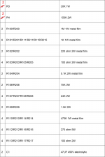
I'm checking through all the components and just came across in George's original Tubelab design: -
R100 - 220K 1/4W metal film
R101 - 1K 1/4W metal film
Why has Stephe (Skunkie designs) listed them: -
R100 - 1M 1W metal film
R101 - 1K 1W metal film
Trying to find reasons for Skunkie value changes. Input impedance? But 1W resistors?
Not wanting to get muddled up, perhaps i need to stick with the original values in Tubelab's design
Last edited:
I personally think higher power resistors sound -slightly- better/less noisy and modern 1W ones are close to the same size and almost the same price. I also usually buy more than I need, for future project stock (buy 10 for the discount), and next time they might need to be 1W. It's easier to just "stock" 1W and 3W values, especially when point to point wiring, which is all I do.I'm checking through all the components and just came across in George's original Tubelab design: -
R100 - 220K 1/4W metal film
R101 - 1K 1/4W metal film
Why has Stephe (Skunkie designs) listed them: -
R100 - 1M 1W metal film
R101 - 1K 1W metal film
Trying to find reasons for Skunkie value changes. Input impedance? But 1W resistors?
Not wanting to get muddled up, perhaps i need to stick with the original values in Tubelab's design
Also I'm building mine with a 100K volume pot on the input, so there is no need for R100 to be 220k as it's simply there as a safety in case the volume control wiper fails.
These are just personal choices I am making for my own build.
Thanks Stephe for your explanations, i'm still working on my BOM listI personally think higher power resistors sound -slightly- better/less noisy and modern 1W ones are close to the same size and almost the same price. I also usually buy more than I need, for future project stock (buy 10 for the discount), and next time they might need to be 1W. It's easier to just "stock" 1W and 3W values, especially when point to point wiring, which is all I do.
Also I'm building mine with a 100K volume pot on the input, so there is no need for R100 to be 220k as it's simply there as a safety in case the volume control wiper fails.
These are just personal choices I am making for my own build.
and will continue to look at the Transformers- Home
- Amplifiers
- Tubes / Valves
- Tubelab SPP first timer build