Thanks for communicating the difference between power and signal grounding, evanc. That clears things up.
So what I need to do then, is connect the power receptacle ground lug to the chassis, and that takes care of power grounding.
The signal is grounded through the board's connection to the RCA jacks.
I'll be connecting the TSE directly to a CD player as music source. Since the RCA jacks are isolated from the chassis, I infer, then, that the board is grounded through the RCA jacks' connection to the CD player (which is itself grounded)?
Last edited:
I'm sorry I am not better at writing what I'm thinking. The RCA inputs both hot and ground go to the board. R1 and L1 are the ground connection for the input signal. R2 and L2 are the hot connections for the inputs. The board is grounded by a wire from the gnd2 connection on the board going to the chassis at or close to the safety ground. I can snap a picture tomorrow.
E
E
Ok, thanks. That makes sense. I think you already provided a pic that shows your star ground point here:
http://www.diyaudio.com/forums/tubelab/277870-tubelab-se-300b-build-thread-4.html#post4420547.
So I can run a wire from Gnd2 to the same bolt that grounds the power receptacle to the chassis, and that should take care of it?
Thanks for your patience, everyone. I just want to make sure I've got this right before I implement it.
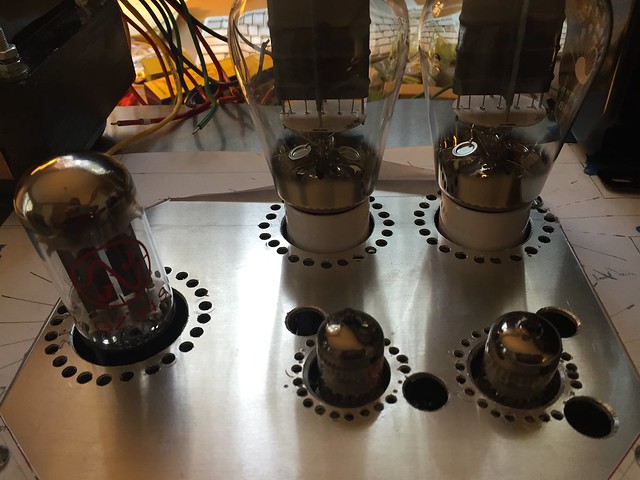 Tube lineup by jeffdrouin, on FlickrChassis is drilled and everything lines up nicely. Definitely looks... er... homemade.
Unwanted or out of position holes can easily be filled with epoxy, sanded flush, and re-drilled, if need be. I recycle my chassis, so I do it all the time. Once it's painted, the repairs are imperceptible.
Generally, filling, curing, and sanding adds about an extra day.
Win W5JAG
Generally, filling, curing, and sanding adds about an extra day.
Win W5JAG
I work with metal at work all the time. Not too bad for a layman, honestly, pretty good.
Do you own a center punch? If not, I think it would solve 97% of your "homemade" issues.
A single flute pointed counter sink will clean up even the smallest of burrs. If using it in aluminum, I would power it with my fingers. If carbon or stainless steel, use a drill at very low (<200 rpm) speed, with light oil for lube.
Phil
Good to know about the epoxy, Win, and thanks for the kind words, Phil.
To mark the hole starters, I used a punch that you have to hit with a hammer (which makes it wander). Wish I'd gotten a sprung center punch for this project.
Anyway, just ordered the Black & Decker rotary tool along with some Dremel reinforced cutoff disks (#426) and an aluminum oxide grinder for deburring.
Just realized I'll need to get some fuses. The fused receptacle/switch I bought is rated up to 250V and 10A. The unit indicates that 250V fuses must be used. Any idea what amp rating I need? How would I figure that out, given that I'm in the U.S. where we have 120V wall outlets?
Finally picked up an automatic center punch. Wow! Way more accurate than the hammered nail set I used for the tube vent holes.
For the next project I'll center the tube and trim pot holes first, and then draw out the vent holes right on the metal, instead of working with a paper overlay.
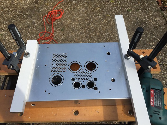
Anyway, the vent holes with be 3/16" and I should be able to drill them tomorrow. Will probably expand the venting to a wider area of the chassis top plate.
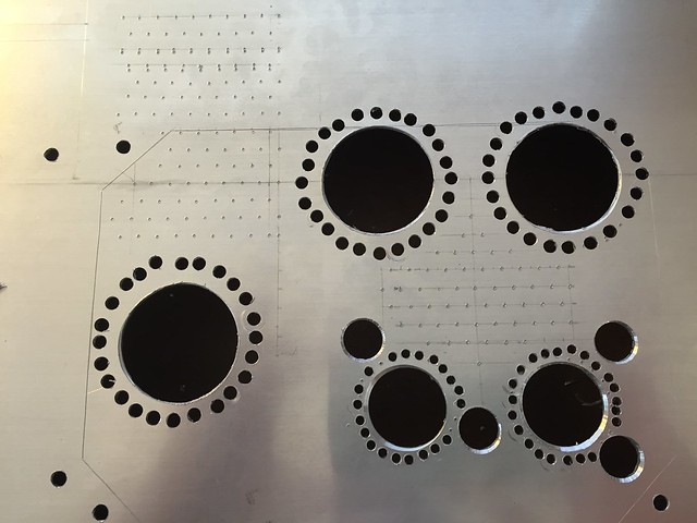 Vent pattern set by jeffdrouin, on Flickr
Dang! I just noticed I missed one.
For the next project I'll center the tube and trim pot holes first, and then draw out the vent holes right on the metal, instead of working with a paper overlay.
Anyway, the vent holes with be 3/16" and I should be able to drill them tomorrow. Will probably expand the venting to a wider area of the chassis top plate.
Vent pattern set by jeffdrouin, on FlickrDang! I just noticed I missed one.
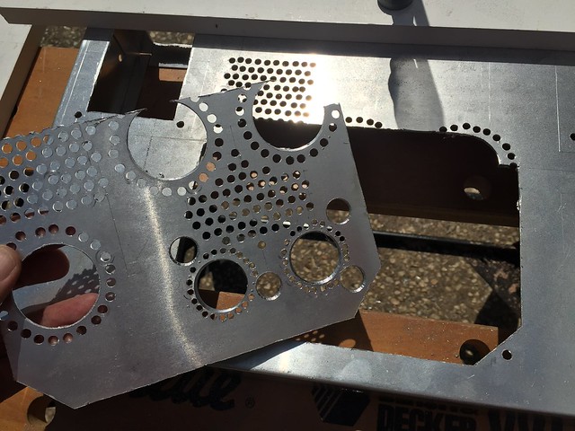
May have been simpler if you used one of these sheet metals and cut the holes for tubes. 
An externally hosted image should be here but it was not working when we last tested it.
Well, I wanted to do something custom, plus for the same outlay of cash I got an addictive new tool!
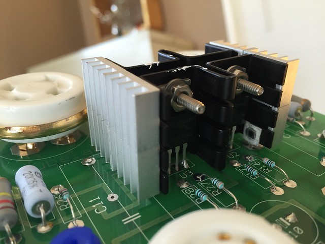
I picked up some small aluminum heat sinks for the mid-board semiconductors. They have thermal tape attached to them. Originally I was planning to remove the tape and attach them with Arctic Silver adhesive but the bond is really strong, so I think I'll leave them be:
 Heat sinks by jeffdrouin, on Flickr
The large sink for the semi-conductors at the edge of the board will be attached with some serious adhesive, though.
I picked up some small aluminum heat sinks for the mid-board semiconductors. They have thermal tape attached to them. Originally I was planning to remove the tape and attach them with Arctic Silver adhesive but the bond is really strong, so I think I'll leave them be:
Heat sinks by jeffdrouin, on FlickrThe large sink for the semi-conductors at the edge of the board will be attached with some serious adhesive, though.
Figured it couldn't hurt. After trying several ways to remove the burrs and ribbons in the drilled and rotary-cut aluminum, I finally got this handy little deburring tool that does a fantastic job for under $7:
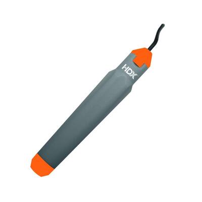
The large tube holes and straight edges are now smooth as butter. The blade swivels around and has one flat side, which is the one you want resting against the surface you're deburring. It works for small holes too, but I tend to have better results with a large drill bit (twisting by hand).
The large tube holes and straight edges are now smooth as butter. The blade swivels around and has one flat side, which is the one you want resting against the surface you're deburring. It works for small holes too, but I tend to have better results with a large drill bit (twisting by hand).
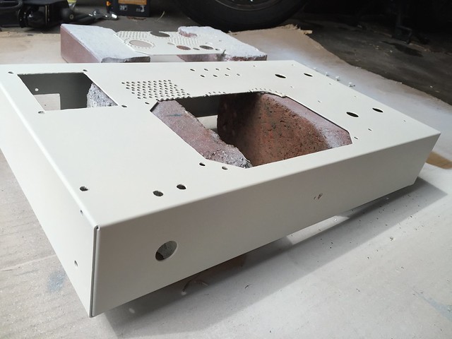
Things are going a bit slow, but I'm almost done with the chassis fabrication. Just have to shape some mounts for the removable top plate, and then it should be ready to assemble and test.
The paint came out decently. Rustoleum matte French Cream. The trigger spray cans do a really nice job covering wide flat surfaces and penetrating into the nooks, crannies, and seams, though they do leave some little paint threads I'll have to clean out. Highly recommended. I also painted some of the hardware for a more finished look.
 Chassis painted by jeffdrouin, on Flickr
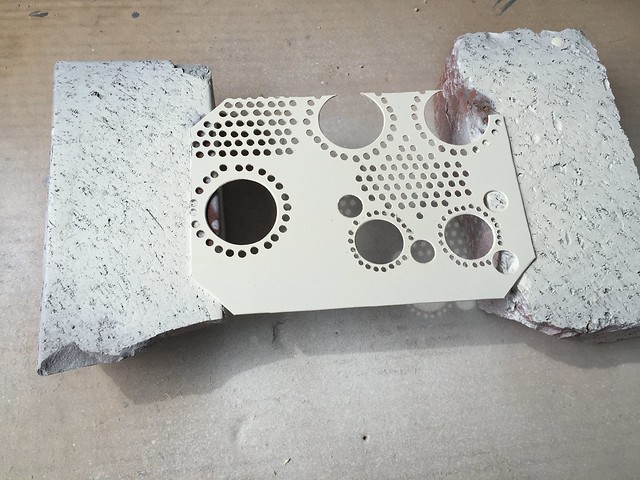 Top plate painted by jeffdrouin, on Flickr
The paint came out decently. Rustoleum matte French Cream. The trigger spray cans do a really nice job covering wide flat surfaces and penetrating into the nooks, crannies, and seams, though they do leave some little paint threads I'll have to clean out. Highly recommended. I also painted some of the hardware for a more finished look.
Chassis painted by jeffdrouin, on Flickr
Top plate painted by jeffdrouin, on FlickrI fabricated a brace to support the OPTs with some aluminum flat stock and L brackets I had lying around. Used the rotary tool to custom shape some 1" washers as top panel mounts that clear the vent holes and surrounding hardware. Hoping to have it wired and ready for the check out procedure tomorrow.
 Brace for OPTs by jeffdrouin, on Flickr
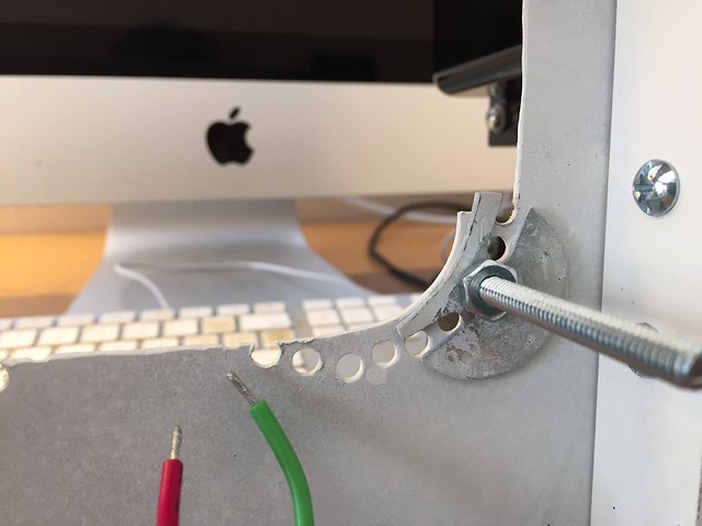 Top Panel Mount by jeffdrouin, on Flickr
Brace for OPTs by jeffdrouin, on Flickr
Top Panel Mount by jeffdrouin, on FlickrI actually deburred the holes so much that it made them too big for he grommets I'd gotten. The edges are very smooth, so I'm not worried about them cutting the wire jackets.
Now I need to wire the magnetics to the board. Is it recommended to tin the wires first?
Also, it seems some people ground the input and output jacks by connecting their ground leads to a kind of rail that runs to the ground point, like this:

Is this recommended?
Now I need to wire the magnetics to the board. Is it recommended to tin the wires first?
Also, it seems some people ground the input and output jacks by connecting their ground leads to a kind of rail that runs to the ground point, like this:
Is this recommended?
Last edited:
- Status
- This old topic is closed. If you want to reopen this topic, contact a moderator using the "Report Post" button.
- Home
- More Vendors...
- Tubelab
- Tubelab SE 300b Build Thread