Thanks for the confirmation, Win and Denny. I think I've got my panel cut/drill plans set. The tube/vent holes can work as starters for the mini hacksaw. Or maybe this is an excuse to get a jigsaw with a 1/4" wide metal-cutting blade. ;-)
 Panel cuts by jeffdrouin, on Flickr
Panel cuts by jeffdrouin, on FlickrThanks for the pointers. I've got a titanium coated stepped drill bit and bi-metal hole saw for the larger holes. Also scored a 29-piece titanium coated drill bit set, in 1/64 increments, at Harbor Freight for $10!
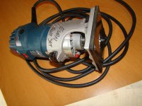
You've got me thinking about rotary tools now, since I'll also have to cut out a rectangle for the PT and the power receptacle. I see a Dremel 200 series tool (which is compatible with their drill press/workstation) for just under $50. Or for half the price there's this one at Harbor Freight. Any experience with these?
For cutting rectangles and a pattern like the one I just posted above, do you think I'd want to use a cutting wheel or metal saw attachment? I don't want too much of a gap between the pieces, but I also want clean, precise cuts.
Last edited:
This is the cut-off wheel I use for making chassis openings... Does a great job after a little practice. If you use one, practice using it in the area that will be cut out, before trying it on the cut line.
Dremel Cut-Off Wheel
Dremel Cut-Off Wheel
Last edited:
Same here, evanc. My plan is to drill access holes for the trim pots and also to place an array of chassis-mounted tip jacks for the test probes. That way I wouldn't need to take it apart to make adjustments. For the trim pot and OPT/Choke wire holes, I picked up a box of 180 assorted rubber grommets at Harbor Freight for like $6. I *love* that place.
These are some sketches of what the tip jack array might look like. To make it simple I could just have jacks for B+, B-, driver tube voltage, and output tube bias, since those are the most likely to get adjusted over time. On the other hand, if I'm going through the trouble to do that, then why not include jacks for all possible tests and be done with it?
There's room for it in the chassis, but I don't know if there would be a detrimental affect with all those wires leading off key places on the PCB.
Chassis layout by jeffdrouin, on Flickr
I'd only have tip jacks for biasing the outputs and drive tube voltage, as those are the only two that are adjustable. Bringing a grid line to a tip jack could cause stability issues.
Output bias shares a common point between the two channels for the reference voltage which is B+, and drive plate voltage uses "ground" (0V) as a reference. If you want to measure B+, you could measure across the common "grounds" for the two measurement points, which are B+ and 0V. You'd only need 6 tip jacks to facilitate these 5 measurement points.
Thanks, Denny. I've seen #426 referenced in a few online threads.
JP, I'd thought about having one black tip jack for the common grounds but liked the pattern shown on the Post-It. I'm probably a week away from dealing with the tip jacks so I'll think about it more until then.
JP, I'd thought about having one black tip jack for the common grounds but liked the pattern shown on the Post-It. I'm probably a week away from dealing with the tip jacks so I'll think about it more until then.
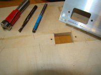
This is how I would do it.....Not the only way just my take on it.
I would not try to get the center and surround from the same piece. The kerf from either a reciprocating saw like a jig saw or a cut off wheel are going to be too thick as well as too raged for my taste.
I would make a pattern and cut out the hole with a jig saw staying well back from the line and then finish to the final size with a router. Either the bearing riding the pattern or the shank of the bit riding the pattern.
Make the center section from a separate piece cut on a table saw or again roughed out with a jig saw and trimmed to a pattern with a router.
Sorry I don't have more/better photos.
Attachments
That looks great, Evan. Love the rounded corners of that rectangle. Thanks for the pointers.
I'm wondering about what kind of wires to use for connecting various parts. I've got 20 AWG solid copper hookup wire of varying colors. Can I use it for all of the following?
* RCA input jacks to PCB and volume attenuator
* Various components to star ground point
* PCB to tip jacks for bias set
I've read that you don't want hook up wire for anything carrying current. Would that apply to tip jacks if you're just testing output tube current bias?
I use both solid and stranded. The stranded has a higher voltage rating (600v), so I use it for the power supply side of builds. Solid, with it's lower rating (300v), for things like RCA connections and volume pot. Solid is easier to work with for me (gimped hands), esp. making twisted pairs. Check the voltage rating... if it's 300 volts, it'll be too low for your power supply. Any wire carrying volts, carries current-Ohm's Law. I've used both for test points w/o any problems...it's a matter of what your measuring as to which to use. I used solid for my bias test points.
Keep in mind the bias test points are nearly full B+ referenced to ground.
Not a problem on my build. I use type 45 tubes with the B+ at 276 vdc. For a 300b build, 600 volt stranded should be used.
Thanks. I've got 600 volt solid.
While marking out all the cuts on my chassis today I noticed the laminations on the PT have shifted a bit:
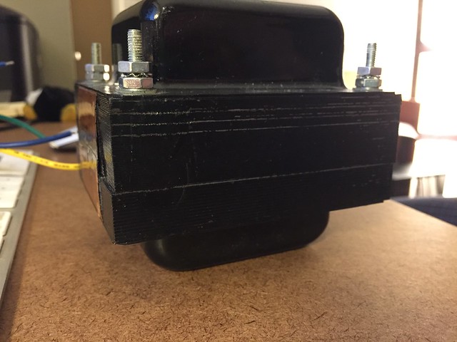 PT by jeffdrouin, on Flickr
Anything to worry about?
While marking out all the cuts on my chassis today I noticed the laminations on the PT have shifted a bit:
PT by jeffdrouin, on FlickrAnything to worry about?
FYI, the manufacturer said the shifted laminations are nothing to be concerned about at all.
Now I'm planning out the wiring and grounding. Unless I'm wrong, it seems I can refer to the first wiring illustration in the Grounding section of the SSE wiring instructions because it's for an instance that uses no CFB, though there will be a couple of differences.

I'm using an all aluminum chassis. If understand correctly, I'll need to make a star ground point on an unpainted patch of the chassis, to which the following items will connect:
* Ground lug of the power receptacle (an integrated switch and fuse unit)
* Ground pad of the PCB
* Negative terminals of the speaker jacks
* Negative terminal of only one (?) of the input jacks
* Metal housing of the choke
* Metal housing of the PT
* Metal housing of both OPTs
To make the star ground point, I'll drill a hole in the chassis (top side, to be protected by the cage) for a bolt/washer/nut. I'll solder the ground wire of each component to a circular lug, fit the lugs over the bolt, and then tighten the nut so that the assembly comes into contact with the chassis. Will that work?
George's instructions state clearly that the metal housing of the choke, PT, and OPTs must be connected to ground. How do I do that? Can I run a wire from a mounting bolt of each component to star ground? Should I solder the wire to the housing somehow? Is it enough that the housings are in contact with the aluminum chassis, anyway, meaning that further grounding is unnecessary?
Thanks!
Now I'm planning out the wiring and grounding. Unless I'm wrong, it seems I can refer to the first wiring illustration in the Grounding section of the SSE wiring instructions because it's for an instance that uses no CFB, though there will be a couple of differences.
I'm using an all aluminum chassis. If understand correctly, I'll need to make a star ground point on an unpainted patch of the chassis, to which the following items will connect:
* Ground lug of the power receptacle (an integrated switch and fuse unit)
* Ground pad of the PCB
* Negative terminals of the speaker jacks
* Negative terminal of only one (?) of the input jacks
* Metal housing of the choke
* Metal housing of the PT
* Metal housing of both OPTs
To make the star ground point, I'll drill a hole in the chassis (top side, to be protected by the cage) for a bolt/washer/nut. I'll solder the ground wire of each component to a circular lug, fit the lugs over the bolt, and then tighten the nut so that the assembly comes into contact with the chassis. Will that work?
George's instructions state clearly that the metal housing of the choke, PT, and OPTs must be connected to ground. How do I do that? Can I run a wire from a mounting bolt of each component to star ground? Should I solder the wire to the housing somehow? Is it enough that the housings are in contact with the aluminum chassis, anyway, meaning that further grounding is unnecessary?
Thanks!
Last edited:
PS -- The star gound point I described would look like this one:
An externally hosted image should be here but it was not working when we last tested it.
....
George's instructions state clearly that the metal housing of the choke, PT, and OPTs must be connected to ground. ...
If the chassis is non conductive, you should separately ground the housings for safety. You are using an aluminum chassis, so unless you use insulating mounting hardware to isolate the housings from the chassis, they are at ground potential provided the chassis is at ground potential.
I run a short wire from the ground terminal of the IEC power connector directly to a solder lug on one of my power xfmr mounting bolts to put the chassis at ground.
Win W5JAG
OK, so since aluminum is conductive, the chassis is *probably* at ground potential. However, to make certain of it I can connect the ground lug of the power receptacle to a mounting bolt on the PT?
I think I understand it but, being a newbie, this is one thing I'd rather not make a mistake about.
Once I turn it on I'll touch test probes to the chassis just to make sure there's no voltage there.
I think I understand it but, being a newbie, this is one thing I'd rather not make a mistake about.
Once I turn it on I'll touch test probes to the chassis just to make sure there's no voltage there.
OK, this passage from the SSE Wiring Diagrams seems to jive with what evanc is saying:
"If a metal chassis is used It should be securely grounded. The best place to make this ground is at the input connector. To avoid hum, this should be the only connection to the chassis. All metal objects (transformers, supplemental cap, choke, volume control, etc) should have a good paint free contact with the chassis. Again, verify this with an ohm meter before using the amp."
I'm uncertain about the apparent contradiction between (paraphrasing) 'input connector should be the only thing connected to the chassis' and 'all metal objects should have a good connection to the chassis.'
So if I run a wire from receptacle ground lug to chassis, how then do I ground the input jacks, PCB, etc.? Would the chassis be at ground potential, meaning that you could put a star ground point basically anywhere else as long as it's in good contact with the chassis? If so, that would seem to contradict what George wrote.
There are two things to think about.
Safety....all exposed metal parts like transformers chokes chassis need to be safety grounded. The ground from the power inlet to the aluminum chassis should take care of this.
Signal ground. I used mini coax but could be a twisted pair from the input RCA connectors to the board. RCA connectors should be isolated from the chassis. There are ground connections right next to the signal connections on the board. There is one wire connecting the chassis to the board. George uses one of the RCA input connectors as this connection. Mine is silent with out any tricks.
Evan
- Status
- This old topic is closed. If you want to reopen this topic, contact a moderator using the "Report Post" button.
- Home
- More Vendors...
- Tubelab
- Tubelab SE 300b Build Thread