Hello Jackinnj,
by their very nature, curve tracers are pieces of kit destined to destroy perfectly good DUTs. Combining one with a PC has to be the ultimate expression of engineering bravery! I have to admit that if I had a curve tracer for valves, my VCM163 would be out the door faster than I could say "mismatched mu."
by their very nature, curve tracers are pieces of kit destined to destroy perfectly good DUTs. Combining one with a PC has to be the ultimate expression of engineering bravery! I have to admit that if I had a curve tracer for valves, my VCM163 would be out the door faster than I could say "mismatched mu."
Wow, is there any more info on this MCTracer?
Thanks!
Thanks!
jackinnj said:
This will tell you more than you need to know -- and is absolutely DIY -- dumps the data into Excel for analysis -- and the software is free:
An externally hosted image should be here but it was not working when we last tested it.
Here lots tube tester, I don´t read Germany, but clear schematics in DIY and in industry.
http://www.jogis-roehrenbude.de/Roe-Pruefer.htm
I´n use AVO CT-160 , I see in Duncanamps and search in my country for about 2 year and found one new in closed radio importer. They use for test valves in radios they sale. I buy it for u$s 50 (really cheap I think).
Sorry, my English is bad.
http://www.jogis-roehrenbude.de/Roe-Pruefer.htm
I´n use AVO CT-160 , I see in Duncanamps and search in my country for about 2 year and found one new in closed radio importer. They use for test valves in radios they sale. I buy it for u$s 50 (really cheap I think).
Sorry, my English is bad.
EC8010 said:by their very nature, curve tracers are pieces of kit destined to destroy perfectly good DUTs. Combining one with a PC has to be the ultimate expression of engineering bravery! I have to admit that if I had a curve tracer for valves, my VCM163 would be out the door faster than I could say "mismatched mu."
Why is something like the Transcendent Tube Analyzer desined to destroy perfectly good tubes?
Edit: Doh! I now see that the Transcendent Tube Analyzer is not a curve tracer. But the question still stands concerning curve tracers.
phn said:Why is something like the Transcendent Tube Analyzer destined to destroy perfectly good tubes?
Because any piece of test equipment is designed with the assumption that the user knows exactly what they are doing. That means that it is perfectly possible to set the equipment to apply 400V across the valve and draw 70mA (which might be entirely appropriate for a KT88), but instant death if an ECC83 was plugged in.
Thanks. I had to know before I blow up something like this: http://www.electricstuff.co.uk/loewe.html
brother_maynard said:Wow, is there any more info on this MCTracer?
Thanks!
What do you need to know? -- the schematics are all there - all you have to do is hook it up to a variable power supply and a computer.
RAT tube tester
Me too! I´ve made a RAT tube tester and It works very well! It´s simple to assembly and very easy to use. I´m no longer using my old TV7 as well! I recommend it and congratulations Steve!")
retailer said:Yes I've built the RAT tester as designed by the Steve Bench. I have a collection of testers ( Eico, Heathkit, Mercury, Precision, AVO MKII, AVO CT160, Supreme, Sencore, Taylor and an ancient Confidence tester), the RAT is the easiest to use by far. It does'nt test directly for shorts but if you watch the anode and screen volt meters as you wind up the current, the meters dip if there is some sort of internal short. I had a bunch of meters on hand so instead of calibrated knobs I've added meters for all the readouts. After using it for about 2 yrs I plan to build another incorporating some extra ideas and also things that I should have done first up.
Me too! I´ve made a RAT tube tester and It works very well! It´s simple to assembly and very easy to use. I´m no longer using my old TV7 as well! I recommend it and congratulations Steve!
I've mounted a couple of sockets on the front so I can plug in a DMM and measure the bias voltage if I need to match valves. My planned rebuild is going ahead now as I have finally found a suitable case from some scrapped medical equipment. My new build will have 100mA anode current capacity, incorporate a shorts and gas test, and have slightly redesigned power supply to eliminate the voltage tripler which lowers the component count. I am going to retain the RAT socket setup (for quick testing common valves) and also add a set of sockets with thumb wheel switches to expand the capacity of valves that can be tested. To be fully self contained my original build incorporated an AC millivoltmeter with digital readout but the new one will have a true RMS AC millivoltmeter using an AD637 true RMS chip. I have just finished designing the boards and should have them etched in the next week or so. Some of the vintage testers that I have are fine well designed instruments but you can't beat modern solid state electronics in this situation. Cheers to Steve Bench for designing such an easy to build easy to use Gm tester.
Mmm...it looks fantastic! As a mater of fact I was a bit concerned with the true AC millivolt readings. The Gm data I got are the fact higher using a standard DMM (max 400hz AC readings) Where did you get the AD637 chip and board from? I also got 90mA anode current lowering R16 from 133 to 90 ohm. How do you incorporate the shorts and gas test?retailer said:I've mounted a couple of sockets on the front so I can plug in a DMM and measure the bias voltage if I need to match valves. My planned rebuild is going ahead now as I have finally found a suitable case from some scrapped medical equipment. My new build will have 100mA anode current capacity, incorporate a shorts and gas test, and have slightly redesigned power supply to eliminate the voltage tripler which lowers the component count. I am going to retain the RAT socket setup (for quick testing common valves) and also add a set of sockets with thumb wheel switches to expand the capacity of valves that can be tested. To be fully self contained my original build incorporated an AC millivoltmeter with digital readout but the new one will have a true RMS AC millivoltmeter using an AD637 true RMS chip. I have just finished designing the boards and should have them etched in the next week or so. Some of the vintage testers that I have are fine well designed instruments but you can't beat modern solid state electronics in this situation. Cheers to Steve Bench for designing such an easy to build easy to use Gm tester.
jmsegui
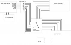
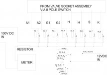
The AD637 chip came from an Ebay seller I think about $US12.00 for a pair, I have drawn the circuit and designed a board for this but not yet tested it. Design came from AD637 data sheets, block diag. would look like this INPUT BUFFER--1KHZ BAND PASS FILTER-AD637--200MV LCD PANEL METER. At present my AC millivoltmeter block diag is as follows INPUT BUFFER--1KHZ BAND PASS FILTER-PRECISION RECTIFIER--200MV LCD PANEL METER. It works quite well, my RAT tester and my calibrated AVO CT160 agree within 5% only the RAT tester is easier to use. If you want the circuit I can send it to you. I am hoping a gas test can be achieved by using a push button switch to short 10k R26, if grid is drawing current ( from gas) shorting R26 will give increase in grid voltage which will result in sudden increase in Gm reading. For shorts aN 8 pole 2 position switch will switch the wires going to the socket assembly from the power supply board to the shorts board
The AD637 chip came from an Ebay seller I think about $US12.00 for a pair, I have drawn the circuit and designed a board for this but not yet tested it. Design came from AD637 data sheets, block diag. would look like this INPUT BUFFER--1KHZ BAND PASS FILTER-AD637--200MV LCD PANEL METER. At present my AC millivoltmeter block diag is as follows INPUT BUFFER--1KHZ BAND PASS FILTER-PRECISION RECTIFIER--200MV LCD PANEL METER. It works quite well, my RAT tester and my calibrated AVO CT160 agree within 5% only the RAT tester is easier to use. If you want the circuit I can send it to you. I am hoping a gas test can be achieved by using a push button switch to short 10k R26, if grid is drawing current ( from gas) shorting R26 will give increase in grid voltage which will result in sudden increase in Gm reading. For shorts aN 8 pole 2 position switch will switch the wires going to the socket assembly from the power supply board to the shorts board
Attachments
Hi,
Sorry for the delay, I wasn't monitoring this thread anymore...
Manual as in test settings? There should be a PDF or XLS on my site if the link is active still.
Here's some more on it that I wrote after:
www.classicvalve.ca/tester.html
Cheers!
soundbrigade said:Geek-man, have you got some kind of manual for your tester? I mean it looks fantastic, no need for a mains transformer with fortyeleven taps and some odd card overlays.
Sorry for the delay, I wasn't monitoring this thread anymore...
Manual as in test settings? There should be a PDF or XLS on my site if the link is active still.
Here's some more on it that I wrote after:
www.classicvalve.ca/tester.html
Cheers!
RAT Tube Tester
Retailer
Very clever AC true RMS design! Thanks a million. Yes please, eMail me a copy of your circuit. About the gas test I think you are right. If grid drives current the Gm would rise.
I will enclose picture of my DIY tester if I can reduce its weight.
retailer said:jmsegui
The AD637 chip came from an Ebay seller I think about $US12.00 for a pair, I have drawn the circuit and designed a board for this but not yet tested it. Design came from AD637 data sheets, block diag. would look like this INPUT BUFFER--1KHZ BAND PASS FILTER-AD637--200MV LCD PANEL METER. At present my AC millivoltmeter block diag is as follows INPUT BUFFER--1KHZ BAND PASS FILTER-PRECISION RECTIFIER--200MV LCD PANEL METER. It works quite well, my RAT tester and my calibrated AVO CT160 agree within 5% only the RAT tester is easier to use. If you want the circuit I can send it to you. I am hoping a gas test can be achieved by using a push button switch to short 10k R26, if grid is drawing current ( from gas) shorting R26 will give increase in grid voltage which will result in sudden increase in Gm reading. For shorts aN 8 pole 2 position switch will switch the wires going to the socket assembly from the power supply board to the shorts board
Retailer
Very clever AC true RMS design! Thanks a million. Yes please, eMail me a copy of your circuit. About the gas test I think you are right. If grid drives current the Gm would rise.
I will enclose picture of my DIY tester if I can reduce its weight.
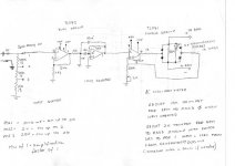
retailer said:May as well post the millivoltmeter circuit while I'm at it
Hello there!
I enclose the TRMS schematic I´ve made a based on your draft. Is that correct? I´ll drive the board this weekend.
Cheers
jmsegui@ya.com
Attachments
jmsegui
This the millivoltmeter with the precision rectifier it is tested and working; yours looks OK. I have drawn a circuit but not yet built a prototype of the true RMS millivoltmeter I will post the circuit if you want.
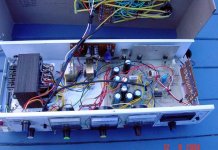
It is better to use 10 turn type trim pot for both they will be easier to set. I put C4 on the RAT tester board then shielded cable to the range switch. R7,R8,R9 mounted on the switch, and more shielded cable to the millivoltmeter board. If you use a moving coil meter for the output indicator you can leave out R10 150R, it is part of the feedback circuit and internal coil resistance of the meter is used instead. I used a LCD panel meter because it has much better resolution than moving coil meter, it is cheaper ($AU9.95) and there is no need to draw a scale for the meter face. As it is my circuit is set for 200mv fsd you may need to experiment with a series R with a moving coil meter. The down side to using a LCD panel meter is that it must have its own power supply, it cannot share a power supply with the same device that it is measuring (ie the millivoltmeter circuit). At first I thought to use a 9v battery, current comsumption is very low and the battery should last a long time, but in the end I settled for a separate regulated 9vdc supply for the LCD meter, no need to open up the tester to change the battery, also battery always seems to go flat when you need it the most. I'm attaching a pic of my tester, I wound my own mains transformer and only used common filament voltages 2.5, 5, 6.3 and 12.6. The two small transformers are for millivoltmeter and LCD panel meter. Millivoltmeter is at the right made on veroboard. Valve sockets are on top. The three meters are for valve current, anode volts and screen volts. Valve current meter is switchable to read 0-10 and 0-50 mA.
This the millivoltmeter with the precision rectifier it is tested and working; yours looks OK. I have drawn a circuit but not yet built a prototype of the true RMS millivoltmeter I will post the circuit if you want.
It is better to use 10 turn type trim pot for both they will be easier to set. I put C4 on the RAT tester board then shielded cable to the range switch. R7,R8,R9 mounted on the switch, and more shielded cable to the millivoltmeter board. If you use a moving coil meter for the output indicator you can leave out R10 150R, it is part of the feedback circuit and internal coil resistance of the meter is used instead. I used a LCD panel meter because it has much better resolution than moving coil meter, it is cheaper ($AU9.95) and there is no need to draw a scale for the meter face. As it is my circuit is set for 200mv fsd you may need to experiment with a series R with a moving coil meter. The down side to using a LCD panel meter is that it must have its own power supply, it cannot share a power supply with the same device that it is measuring (ie the millivoltmeter circuit). At first I thought to use a 9v battery, current comsumption is very low and the battery should last a long time, but in the end I settled for a separate regulated 9vdc supply for the LCD meter, no need to open up the tester to change the battery, also battery always seems to go flat when you need it the most. I'm attaching a pic of my tester, I wound my own mains transformer and only used common filament voltages 2.5, 5, 6.3 and 12.6. The two small transformers are for millivoltmeter and LCD panel meter. Millivoltmeter is at the right made on veroboard. Valve sockets are on top. The three meters are for valve current, anode volts and screen volts. Valve current meter is switchable to read 0-10 and 0-50 mA.
Attachments
- Status
- This old topic is closed. If you want to reopen this topic, contact a moderator using the "Report Post" button.
- Home
- Design & Build
- Equipment & Tools
- Tube testers which is the best?