A 12AT7 is never going to be as linear as a 12AU7 or 12AX7, because it is a television/FM radio frequency changer
Yes, a 12AT7 in an RC coupled amp has a typically higher level of 2nd harmonic than the 12AX7. The 12AU7 and its variants are all over the place distortion wise, and many have far more 3rd than the 12AT7. I have yet to find a reliable low distortion operating point for the 12AU7 that works across a wide range of tubes, although I have found a few tubes that show very low distortion.
Real measured data on dozens of 12AT7's working into a CCS || 220K grid resistor showed them to be remarkably more linear than a similar sized collection of 12AU7's under the same conditions. The 12AU7 also doesn't have enough gain to drive a 6550 to full output from a CD player. The 12AX7 has the gain, and falls into the same range distortion wise, under the SAME CONDITIONS, but costs more, so the 12AT7 is what I chose for the SSE.
I considered, and tested all sorts of "12AT7's" military, commercial, industrial, consumer grade, and used junk. Ditto the 12AU7 and AX7. They are all available, and someone somewhere will stick one into your amp design, you must test for it.
Merely swapping the plate load resistor for a CCS will generally improve the distortion somewhat. The degree of improvement depends on the total load impedance that the plate of the tube sees. This is the || combination of the load resistor (or CCS), the grid resistor of the next stage, C miller of the next stage, and other stray and unwanted loads. Swapping the plate load resistor for a CCS will improve one aspect of these load impedances without changing the others.
The SRPP, Mu Followers, or other CCS / buffer circuits work to improve all of them. I have found that the best real world circuit is a CCS AND a follower (tube or mosfet). Placing the coupling cap in between these elements will also eliminate blocking distortion and many of the real or perceived effects caused by capacitors in the signal path since the cap is now working into a very high impedance.
Matched tubes or matched sections in a dual tube aren't!! Make some real world measurements on a few (it won't take many) 6AS7's, 6080's or other regulator dual triodes. They are not even close. Some are so bad that they don't even make good single tube push pull amps.
Granted a dual tube will have the same parts in each section, and each section will be assembled by the same human. But the assembler was still human, and humans do have bad days. Some dual triodes from the final days of tube production might have been partially built on machines. Maybe they built a few that were perfectly matched. They are still 50 years old. Yes, new 12AX7's are still being made......test a few are they well matched? At what operating point? Over what current range? How long will they stay matched?
I spent 41 years in the RF design world. There we have reasonably accurate device models, and good design software to model EVERY aspect of the signal flow. This is required for designing 2 GHz RF IC chip design where every test chip pass costs hundreds of KILLOBUCKS!!! I spent considerable time testing and verifying these models in real world circuits. This is also necessary with new technology especially when you don't know how the models were developed or under what conditions they were verified and tested (if they were at all). I found that the people I worked with fit in one of two categories. They were either the "simulate and calculate" people who worked with computers, or they were "build, test, and iterate until it works" people who worked with soldering irons and a Digikey catalog. I was one of the few people who worked in both worlds.
Vacuum tube design is another one of those places where both worlds are needed. Many, if not MOST of the tubes we have today just flat out DON'T MATCH the data sheets. Our Spice models vary from poor to quite good, as long as you keep the tube in the "normal" operating range. Don't expect grid current or screen drive to be modelled correctly.
Ever crack open a dozen or so tubes with the same number on them and see maybe 4 or 5 totally different designs. How can these all act the same over all conditions. Bust open some 807's, or just look through the glass. The 807 was derived from the 6L6GA. Since then the various manufacturers have stuffed the 807 glass with 6L6GA, 6L6GB, 6L6GC, 7027, 7027A, and every one of the other 6L6 variants ever made, with or without the RF shielding. I got a large lot of tubes that were rescued from the dumpster and it contained thousands of broken 807's. I took a lot of them apart.
Look at the 6HB6 thread. Users are finding identically marked tubes with totally different operating points. There are verified examples of 6B4 DHT's made with pentode sweep tube guts inside them. These were made for a government or military contract somewhere and now found on the surplus market. I have seen other examples of "glass stuffing." It is simply not possible today to design any tube equipment based on spec sheets alone. Look at the data sheets provided by todays Russian and Chinese tube makers. They are simply copies of old US tube data sheets. Test a few and see if they match.
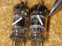
SY mentioned the JJ 12AT7. Look at the plate structure. Does it look any thing at all like a 12AT7? No. Where have you seen it? Yes, it is from a 6DJ8/6922. The grid is also much shorter than a 12AT7. Yes, it does work quite well as a 12AT7 in most audio amps, but will it work in a radio or TV tuner as a 12AT7???????
Aha, mystery solved!SY mentioned the JJ 12AT7. Look at the plate structure. Does it look any thing at all like a 12AT7? No. Where have you seen it? Yes, it is from a 6DJ8/6922.
If I could find a pair of "matched" tubes like these in a box of about 1000 military spares, could I believe that enough care in workmanship was taking place to ensure that every thing was exactly the same for both halves of a dual tube?
These were military grade tubes from the post WWII era. They are industrial numbered (4 digit) 6AG5's. I don't remember the type number.
Why are there "spare" heaters inside the tubes? I don't know, but it was common practice in the days of assembly line work to count the number of parts a worker used before and after their shift as a means of judging worker throughput. I saw this practice used in the early 70's on the HT220 board stuffing line. Workers would take handfuls of components with them to the bathroom and flush them to make their "rate" look better. Management wondered why the numbers never added up.
Can you find this in the data sheet?
Attachments
Last edited:
SY:
How does one contact you?
Use the email function of the forum- I hate the PM system so don't use it, but I have email enabled.
Care to post the formula which you believe - and its source or derivation? Interestingly, Merlin saysKeit said:That formula is completely wrong. Care to post the derivation?
Merlinb said:Yes, that is the formula for the 'optimum' load impedance that gives balanced conduction in the two triodes.
I "have another chance"? To do what? Grovel at the feet of a master? Respond to your bad manners and condescension?Keit said:Having read a great number of your posts, I certainly respect your knowlege. So I won't post my version yet - you have another chance.
The usual way a technical debate proceeds is that someone says something (e.g. posts a formula) and then someone else says "That is incorrect. Here is my formula: ...".
"That is wrong, try again" is what you might say to a particularly dim or lazy student who has exasperated you.
Which is what I found for the symmetrical case of unbypassed cathodes. This is significantly less than for an active load with unbypassed cathodes, so the SRPP connection is doing something. When the lower cathode is bypassed the output impedance is in the region of ra/3 - rather higher than some people expect. This is because the CF action of the upper triode is heavily modified.Merlinb said:This simplifies to approximately ra/2.
As I said, I will recheck my algebra.
The formula I arrived at is Zopt = (mu x Rk - ra)/2.
Yes, that is the formula for the 'optimum' load impedance that gives balanced conduction in the two triodes. At least if they are assumed linear.
We also need to know the SRPP output impedance. For this I have
Zout = (r'a1 + Rk) ra2 / (r'a1 + r'a2)
where r'a1 is the effective anode impedance of the lower valve and r'a2 is that for the upper valve.
Hmm... assuming ra1 = ra2 = ra, and Rk1 = Rk2 = Rk, and mu1 = mu2 = mu, I get:
Zout = [ ra(ra+Rk) + raRk(mu+1) ]/ 2[ra+Rk(mu+1)].
This simplifies to approximately ra/2.
As I said, I will recheck my algebra.
Maybe all of us

From the extraordinary article by Merlin, for the unbypassed SRPP
Rload = [Rkoptimum (μ -1) - ra] / 2
Zout = {(ra + 2Rk) [ra + Rk (μ +2)]} / [2ra + 2Rk (μ + 2)]
Even Merlin's notation is clear, very good work, chapeau!
Keit
So far you have not proved nothing, and your attempt to cover the sun with your hand is just pettifoggery.
Please, be at your high and begin to post as an electronic engineer instead as a cheater lawyer.
This should be a serious technical discussion about tube regulators.
So far you have not proved nothing, and your attempt to cover the sun with your hand is just pettifoggery.
Please, be at your high and begin to post as an electronic engineer instead as a cheater lawyer.
This should be a serious technical discussion about tube regulators.
A 12AT7 is never going to be as linear as a 12AU7 or 12AX7, because it is a television/FM radio frequency changer, where non-linearity is a requirement, to get an IF output from modulating the input from teh aerial with the local oscillator.
Before you bring this up again, please note that these triode mixers of which you fantasize were typically LINEAR mixers, not detector-type mixers. I presume that you are referring to the Pullen mixer and its derivatives. It is a great low noise mixer of the day. Look it up.
Hey wait a minute...I came to this thread researching tube regulators! WTF!
Last edited:
Hey wait a minute...I came to this thread researching tube regulators! WTF!
Hahaha I know!!!!
Since I decided to do the phono section I ditched the tube regulator idea. Consensus is that they are too noisy for this application. I do plan to use them in something, maybe a power amp in the future.
I don't care that the thread got derailed. It has been an interesting thread to say the least. Seems like all but one member is convinced on the merits of a regulated supply. Then again that particular member seems to like to go against the grain. What I do not like is the way he talks to others on here. I think we all know whom I speak of. We all know DF96 is a very intelligent individual, he doesn't deserve to be talked to like that, nobody does.
Good discussions and great contributions by all!! Lets just keep it civil ladies and gents
Of course, an unregulated supply can sound decent on phono. You can get a fairly quiet DC supply with caps and chokes but for ultimate low noise performance, if that is your goal, regulators are kinda hard to argue with.
I'm building a low noise preamp right now and I'm tempted to go with a tube regulator or a tube rectified mosfet regulator with mosfet capacitance multipliers on the phono board to decouple the stages. I like the tube rect for slow turn on and reduced switching noise. I'll have a separate dual bobbin heater trans for a regulated 6.3V.
The simple mosfet regulator shown here might be the easiest way out. No so much an absolute voltage regulator as a de-rippler. Is this Roger Modjeski's design?
RJM Audio - Tube passive phono preamplifier
A so-called linear mixer works by using some second-order distortion in the device characteristic. The last thing you want in a 'linear' mixer is excellent device linearity!Joe Roberts said:Before you bring this up again, please note that these triode mixers of which you fantasize were typically LINEAR mixers, not detector-type mixers.
Very unlikely. The 12AT7 was often used as a self-oscillating mixer in VHF FM front-ends. This used one triode. The other was typically used as an RF stage. The Pullen mixer used two triodes and was intended more for HF applications, not VHF.I presume that you are referring to the Pullen mixer and its derivatives.
By the way, I think Merlin's SRPP formulae assume that there is a 2Rk resistor above the upper anode. I used to be puzzled why this was included, but now I think I understand that it ensures that both valves see the same anode-cathode voltage swing under balanced conditions. My formulae omit this, as most SRPP omit the resistor. As a result, he will get slightly different answers from me - but well within the sort of tolerances which we expect with valve circuitry.
A so-called linear mixer works by using some second-order distortion in the device characteristic. The last thing you want in a 'linear' mixer is excellent device linearity!
Correct. I think they did this by reducing the plate voltage drastically to almost starved plate conditions. The point I was making is that it wasn't used as a detector way into non-linearity.
I used the cathode coupled type 12AT7 mixers in HF receivers, way back when, mostly replacing multigrid 50s designs that were noisy as hell. Been a long while since I've fired up a tube HF receiver or even thought about them, but the thread is so lively I decided to jump in.
Now you got me interested in the topic again so I'll go research it some more. I think I have a few Collins and Mackay Marine receivers in storage.
re:RIAA and cascade triode pairs with say an unregulated RC/LC supply, is it advantageous to employ DC feedback from the 2nd stage plate to the first stage cathode or does that create new problems? IIRC, Chris Paul made an active highpass configuration with the line stage in his "Greening of the Dyna PAS"
subjectively, an anode follower seems like a good thing for a low gain line stage in RIAA preamps.
subjectively, an anode follower seems like a good thing for a low gain line stage in RIAA preamps.
Since I decided to do the phono section I ditched the tube regulator idea. Consensus is that they are too noisy for this application. I do plan to use them in something, maybe a power amp in the future.
Don´t ditch it yet!! To "re-rail" the topic, I too was thinking of using VR tubes for a preamp and today I did some actual measurments on an 874 tube (first VR tube) and a simple neon lamp (the small ones). I hooked them to my DC power supply through a 7,1K resistor and put a 1meg resistor in parallel as a load. (not much of a load though lol)
Concerning noise, putting a 100nF cap in parallel with both the noise was just under 1mv, but it was pretty nasty as it included RF and was jumping all around. Noise didn´t seem to vary with operating current. Nevertheless, if you include a subsequent filter stage, coupled with the amplifier stage psrr noise shouldn´t be an issue.
As a sidenote, I even put a 250nF cap in parallel expecting an inevitable relaxation oscillator, but the 874 never entered oscillation, and the neon lamp did so for a bit, but only as the DC supply was set marginally higher than the firing voltage, any higher and oscillation ceased. So oscillation, not a major concern IMO.
I also measured the impedance of the 874, which varied with applied ac voltage but was around 350ohm, which is around what merlin measured in a number of VR tubes in his PS book. What this implies is that the DC fed to the VR tube has to be reasonably filtered, you can´t just throw 20 volts of ripple at it and expect a flat output.
I'm building a low noise preamp right now and I'm tempted to go with a tube regulator or a tube rectified mosfet regulator with mosfet capacitance multipliers on the phono board to decouple the stages. I like the tube rect for slow turn on and reduced switching noise. I'll have a separate dual bobbin heater trans for a regulated 6.3V.
I am designing a new preamp, with a hybrid cascode MM/MC phono stage a la Allen Wright, as SY pointed out, cascode has very poor PSRR, then I must go for a shunt regulator.
I also like valve rectifiers, and MOSFET/OpAmp regulator as it is easy and cheap, really I cannot understand why people complicate live with enormous (and in some cases noisy) inductors, I found the SS solution more elegant and functional.
DC heater regulator is mandatory, and the smart trick used by SY with +/- 6V3 to improve common mode rejection, I strongly dislike LM317/337, so a regulator a la Walt Yung/Jan Didden seems to me a better choice.
No offence intended SY.
I also like valve rectifiers, and MOSFET/OpAmp regulator as it is easy and cheap,
really I cannot understand why people complicate live with enormous (and in some
cases noisy) inductors, I found the SS solution more elegant and functional.
Yeah but chokes have their own special antique charm...but I am getting tired of antique charm more and more as I get older myself.
I bought a couple very nice LT1083 reg boardsfor the heaters from the Big E for about 12 bucks each stuffed and shipped.
[ The 12AT7 was often used as a self-oscillating mixer in VHF FM front-ends.
DF96, I'm finding the triode self oscillating mixer in Euro car radios, mostly. Seems there were series of tubes built for this purpose by Philips et al.
Has anybody seen this config in US VHF gear? Most of the VHF stuff I have played with is too "fancy" for this approach, hifi FM tuners and professional/mil radios. Mini UHF triodes with external oscillators (with AFC for BC FM) are most common implementation.
Just looking to learn something new.
Back to the originial topic, whatever it was...oh yeah, tube regulators.
...I cannot understand why people complicate live...
...I strongly dislike LM317/337, so a regulator a la Walt Yung/Jan Didden seems to me a better choice.
No offence intended SY.
I will not comment.
Yeah but chokes have their own special antique charm...but I am getting tired of antique charm more and more as I get older myself.
Chokes get older too, due to DC magnetic field.
I will not comment.
Maybe you must be cynical one more time, it could be enlightening.
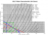
Vacuum tube design is another one of those places where both worlds are needed. Many, if not MOST of the tubes we have today just flat out DON'T MATCH the data sheets. Our Spice models vary from poor to quite good, as long as you keep the tube in the "normal" operating range. Don't expect grid current or screen drive to be modelled correctly.
This hasn't been my experience at all. I have found that the actual implementations have been within +/-5.0% of the design nominal values. Here is the design of the LTP for the Vixen. These are RCA data sheets, and implemented with Sovtek 6SL7s. The design nominal gain is 50 (25 for an LTP) and the measured gain was 25 -- a 0% error. Yes, sometimes that happens. Still, I haven't seen hollow state designs turn out any worse than solid state designs: always within a +/-5.0% margin of error.
It is simply not possible today to design any tube equipment based on spec sheets alone. Look at the data sheets provided by todays Russian and Chinese tube makers. They are simply copies of old US tube data sheets. Test a few and see if they match.
At least the Sovtek 6SN7s and 6SL7s have stuck quite closely to the old data sheets. As for other examples, well, I dunnow since I haven't used these as the designs I've done so far haven't used other Russian/Chinese types.
Attachments
- Status
- This old topic is closed. If you want to reopen this topic, contact a moderator using the "Report Post" button.
- Home
- Amplifiers
- Tubes / Valves
- tube regulators