I finally am starting to build my preamp and because I do listen to vinyl I will most likely go with the FVP-5. I originally was going to an Aikido linestage.
I was also going to use a Maida style regulator to get my 300V B+ and then I saw how cool an OD3 looks. Is there anything wrong with using two of them in series for the 300V?
Has anybody had any good experience with tube regulators or should I just stick with my original plan of using a Maida style HV regulator?
I will post a schematic when I get things squared away. I am thinking full wave tube rectified, C input filter, choke, C , resistor, OD3, OD3 and tap from between the resistor and first OD3.
Your choice of regulator may depend on the particular load you are supplying, but generally a 0D3 shunt regulator should work just fine in preamp service. Personally, I like supplying the regulator through a DN2540 current source, which then feeds the parallel gas tube and load. Yes, you can definitely series them for 300V. I have attached a partial schematic of what I use in my power amp. Nice thing about this design is your upstream C-L-C or whatever really is not that critical; the CCS takes the brunt of the ripple.
Attachments
When putting gas regulators in series you may have to think about how to provide the starting voltage. Until one fires, each is effectively open circuit so the other sees little or no voltage. You can do clever things with a silicon diode and a couple of high value resistors so the regs are effectively in parallel before firing and in series after firing. I saw this on the web somewhere some years ago, but I can't remember where.
Why do you need a regulator for a preamp?
Tube circuits are AC coupled, so all that is required in a HT supply is a low impedance and low hum. These needs are met by sufficient shunt capacitance and series resistance.
However, if you do go ahead and use gas regulators:-
1. You will need a shunt resistance in parallel with one of a series pair, to ensure the other one starts, which will then start the shunted one.
2. Gas tubes are inherently noisey. (In fact they were once commonly used as white/random noise sources, not just as voltage references & regulation.) You will need adequate post regulator filtering to keep the noise out of your preamp circuits. Yep - you've guessed it - once you have the filter, you don't need the gas tubes.
3. Be cautious about NOS gas tubes. Manufacturers used to include a small amount of something radioactive, to assist reliable starting. The radioactivity won't hurt you (it's minute and also won't penetrate the glass.) However, a NOS tube 40 or 50 years old will have seen its radioactivity decay and starting may be less reliable or need a higher voltage than the datasheet suggests.
4. Incident light also assists gas tubes to start. In a tube not so old it doesn't make much diffrence, but in old tubes it may. So you can be caught - a power supply working just fine on the bench during testing, but not working right when you enclose it in your nice cabinet, or dim the lights so you can enjoy the pink/orange glow.
Regulated HT for a phono preamp can be useful, to prevent mains voltage variations causing woofer flap due to high LF/subsonic gain.
Are you serious?
There is little point in extending bandwidth below 30 Hz. While many books give the human hearing range as extending down to 15 Hz, the sensitivity of the ear is very far down at that frequency. Extending the bandwidth in a tube amp too far down leaves it susceptable to other troubles like post-transient paralysis due to grid blocking.
Vinyl records cutoff at well before 30 Hz. AM and FM radio always had almost brick wall cutoffs at 50 Hz - not many noticed. Same with movie sound, until Mr Dolby.
If you are serious, just make the HT bypass electrolytic bigger. Capacitors are available at low prices and high capacities that would amaze an old time tube circuit engineer. Or just make the HT series feed resistor bigger. DC regulation is not a concern in low level stages.
Are you serious?
John Atkinson replied to a reader's query on this topic -- not the music but the physics of tonearm effective mass/cartridge compliance-resonance:
Bass cone flap | Stereophile.com
When putting gas regulators in series you may have to think about how to provide the starting voltage. Until one fires, each is effectively open circuit so the other sees little or no voltage. You can do clever things with a silicon diode and a couple of high value resistors so the regs are effectively in parallel before firing and in series after firing. I saw this on the web somewhere some years ago, but I can't remember where.
Agreed, this was addressed in the schematic above with a high value resistor across one of the regs. Consistent and reliable striking.
John Atkinson replied to a reader's query on this topic -- not the music but the physics of tonearm effective mass/cartridge compliance-resonance:
Bass cone flap | Stereophile.com
This is why the IEC long ago amended the RIAA curve to include a low frequency roll off. The correct solution is not to add a regulator, the correct solution is to implement the correct IEC equalisation.
Unfortunately, it must be said that commercial implementation, and electronics magazine articles, of the RIAA/IEC equalisation usually shows what are obviously the components for the two mid-band corner frequencies. There is no specific capacitor included to provide the IEC LF roll-off - because a coupling capacitor can do that. It tricks a lot of people, who go for precision in equalisation to RIAA specs and forget the specified LF rolloff.
On vinyl, there is nothing much signal-wise below 50 Hz. What there is has been recorded assuming the IEC roll-off is in-circuit in playback. The only stuff significant below 50 Hz is tone-arm resonance, warped record induced slew, and turntable rumble (including in some cases rumble in the cutting lathe!). So, best to cut off below 50 Hz.
One of the many advantages of CD's is that there IS signal below 50 Hz, and no rumble. So they soudn a little more natural and have a little more ommph. Unless they are a re-issue of old recordings from the vinyl age.
Last edited:
Let us do some sums.
Take a typical phono preamp with 5mV sensitivity at 1kHz. That means 0.5mV sensitivity from around 50Hz down. The extra IEC rolloff and/or coupling caps in the system will roll things off from about 20Hz, but there remains a region where the LF rolloff will not be very large. Some 'audiophiles' believe they and their speakers can work down to 10Hz or lower but we will ignore them for now.
Mains voltages can vary over quite small timescales. Lets assume a variation of 1%, so perhaps a couple of volts peak-peak on the HT rail. Let us assume a first-stage voltage gain of 30, so the LF sensitivity at the anode is 30x1.5mV=30mV. We have to ensure that a volt of signal on the HT rail results in much less than 30mV at the anode. How much less? As a wild guess I would say at least -40dB and -60dB if we can; some might argue for -70dB. Pick the middle and say we want -50dB below peak signal, so then we need PSRR of 80dB in the first stage in the 20Hz region. That means a time constant in the region of 80s for a single stage (which would take a couple of minutes to stabilise after switching on), or 0.8s for two stages of decoupling. Two stages of 10k plus 100uF would do it.
Yes, big caps would do it for the 20Hz region. What about 1Hz? Well, you can reasonably hope that the LF rolloff in the system would compensate for the lack of attenuation provided by the decoupling. So two LF rolloffs at 20Hz (ish) would be required - but many systems only have one dominant rolloff.
Sorry this is a bit rambling (I am thinking out loud), but my conclusion is that if you want to avoid cone flapping then you need one or more of the following:
1. a regulator
2. humungous great decoupling to at least the first stage, and just one dominant LF rolloff in the system
3. two stage decoupling (still using fairly large values) and two similar LF rolloffs (one of which could be in the phono preamp)
It seems to me that using a regulator is a simple and cheap way of achieving the goal. Heavy decoupling with significant series resistance can sometimes lead to motorboating.
I was also going to use a Maida style regulator to get my 300V B+ and then I saw how cool an OD3 looks. Is there anything wrong with using two of them in series for the 300V?
No, not at all. Just make sure you include a 1.0M resistor between the DC rail and the bottom VRT. This will ensure that both strike.
Has anybody had any good experience with tube regulators or should I just stick with my original plan of using a Maida style HV regulator?
I've used hollow state active regulators as screen supplies, in two different topologies. Both are excellent performers.
Attachments
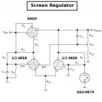
I have read other discussions on how the gas regulators can be noisy, probably not the best idea when making a phono preamp. I see ZigZagflux you have been using them in a power amp so the noise isn't going to be as much of an issue. I will make note that a high value resistor is needed to strike one of the gas regulators when using them in series. I also noted that you have one .047uF cap across both regulators, datasheet says .1uF max. Makes sense, a .1uF cap across each regulator in series equals .05uF per. Maybe my next power amp i can use some for screen regulation.
I will most likely just use a SS regulator. Really the only reason for using the OD3 was because I thought they look cool.
DF96, I am still trying to understand what you said. I will have to sit down with pen and paper and work it out. I might need a specific example or further clarification.
Capacitor value is chosen so that: Rload*C >> 1/f Making the time constant for discharge longer then the time for charging will ensure low ripple. Usually for full wave rectification here is .0083s for a time constant (1/120). I realize this is for the doubling of line power transmission 60Hz*2=120. But you are not talking about filtering the 120Hz pulses I suppose. You are talking about the resonance of the tone arm and cartridge creating infrasonic signals and having to filter them? Or are you talking about the change of mains voltage causes a change of voltage on the HV secondaries, this voltage change can be looked at as and alternating current? Is this sinusoidal in nature? This change in voltage is much smaller on the anode due to the potential divider effect of the load resistor and anode resistance? Since we are dealing with such small signal voltages coming from the turntable these small voltages from the power supply not being regulated showing up on the anode get amplified and cause the woofer flap? Can you show me the math on how you got the 80s for the time constant? Sorry for all the questions. I am still trying to learn and fully appreciate all the advice I get on here.
.... which brings me to a favourite rant: RIAA stages designed to perform down to say 30Hz with exemplary accuracy - and then left to continue the extra amplification to goodness-how-low. Folks going for high-cost tts to be rumble-free as far as that is possible, while the cure could have been a few $ of components for the same effect - as Keit said.
Not popular I know, but I use 'active' RIAA circuits (i.e. the RIAA circuit in a nfb loop). With correct proportioning of already included R-Cs one can get a handy cut-off below 30 Hz, and with just one R-C extra one can readily get l.f. attenuation of 20 dB/octave starting right at the turn-over frequency. Not popular because the response depends to a degree on the loop gain, but that can be managed to well within active device tolerances. (I am a desciple of keeping things not involved in sound OUT of the audible pass band, irrespective of their origin.)
Not popular I know, but I use 'active' RIAA circuits (i.e. the RIAA circuit in a nfb loop). With correct proportioning of already included R-Cs one can get a handy cut-off below 30 Hz, and with just one R-C extra one can readily get l.f. attenuation of 20 dB/octave starting right at the turn-over frequency. Not popular because the response depends to a degree on the loop gain, but that can be managed to well within active device tolerances. (I am a desciple of keeping things not involved in sound OUT of the audible pass band, irrespective of their origin.)
Sorry guys, a 30 Hz. cut off is (IMO) unsatisfactory. A LP with 32 foot organ stops does go there and lower. ") OTOH, if a "standard" double bass, which goes down to 41 Hz., is all you need, the 30 Hz. number is OK.
OTOH, if a "standard" double bass, which goes down to 41 Hz., is all you need, the 30 Hz. number is OK.
Both G_D and the Devil are in the details.
Numerous good and bad implementations of both the passive and active RIAA EQ methods can be found. Passive tends to do better in the overload dept. FWIW, I would want a HIGH gm FET voltage follower driving active RIAA EQ circuitry.
OTOH, if a "standard" double bass, which goes down to 41 Hz., is all you need, the 30 Hz. number is OK.Both G_D and the Devil are in the details.
Numerous good and bad implementations of both the passive and active RIAA EQ methods can be found. Passive tends to do better in the overload dept. FWIW, I would want a HIGH gm FET voltage follower driving active RIAA EQ circuitry.
As for gas discharge regulator tube noise, a 0.047 muF. film cap. across the entire stack's ends takes care of things. The value of the noise suppression cap. can't be particularly large, as highly undesirable relaxation oscillation will start.
No, it doesn't. That will not remove the LF component of the noise. Regulated power supplies aren't normally used with preamps. They are used in applications were a power tube screen requires a steady voltage, or in electronic instrument, oscilloscopes etc where DC precision is required.
And even in those cases, two measures are always taken:-
1) A capacitor is installed to bring the regulator loop gain down to unity. In Miles' midle circuit this is C2, in his rihght hand circuit it is C3. This capacitor does two jobs: it makes the regulator stable (as in stopping it oscillate), and it stops the regulator amplifying the gas tube noise.
2) A electrolytic is placed across the output of the regulator.
Regulated power supplies aren't normally used with preamps.
Really?
Sorry guys, a 30 Hz. cut off is (IMO) unsatisfactory. A LP with 32 foot organ stops does go there and lower.
Sorry Eli, you are quite wrong. You don't hear 30Hz and below very well at all. In things like pipe organs and double basses, you hear the harmonics. It is a matter of fact that if the ear/brain hears a harmonic structure, it "fills in" the fundamental.
You can do 2 simple experiments:-
1) connect a sinewave oscillator to an amplifier of reasonable power output and connect the map to a loudspeaker of known good bass response. Ensuring you don't overload the system, start with 800 Hz at a good loud level. Gradually turn down the oscillator frequency. You'll find that by the time you get down to 50 Hz, the speaker cone travel is quite large, but the percieved level of 50Hz in your ears is very low. Turn the oscillator down to 30 Hz. You proabbly won't hear a thing, but that speaker cone will be really pumping.
I've done this test many many times as it is a good way to show up the slightest speaker faults such as air leaks or voice coil poling. Because of the large cone travel, air leaks and voice coil poling makes noises that are clearly audible in a quiet room, and are not in the slightest masked by the 30 Hz.
2) Play a CD containing a modern recording of things like organs, double basses, etc though a good high quality audio system. Switch in a 2nd order 40 Hz low pass filter. You'll find there is an audible difference in sound character, but it is quite subtle.
Really?
Yes, really. Except for maybe some misguided souls making home-built amps maybe. They come under that same category as the few folk that insist on CCCS cathode biasing, SRPP preamp stages, and other snake oil stuff. Those few make a lot of posts on diyAudio though.
- Status
- This old topic is closed. If you want to reopen this topic, contact a moderator using the "Report Post" button.
- Home
- Amplifiers
- Tubes / Valves
- tube regulators