Still, as you know, many DIYers do really use DHTs in preamps. I believe that the linearity is the chief attraction.
My own suspicion is a bit more cynical.

My own suspicion is a bit more cynical.
Yes, I remember it...
Apropos direct comparisons of DHT vs IDHT - the difference is real when we need a large-voltage-swing for a power-valve's grid driver. Compare real curves for EL34 (triode) etc. These are in turn better than most smaller scale triodes, when the required swing reaches substantial levels..
No one would disagree that a 300B is more linear than small recieving tubes. But this thread is about preamps.
The price of a 300B alone would discourage almost every one from using it in a preamp - where the distortion for even a 12AU7 is likely to be much less than later stages of amplification anyway. Forgetting for the moment that a 300B has a mu of only 4 - so noise is going to be an issue.
I used the 12AU7 as an example because it IS a common preamp tube, as is the 12AX7. As far as curves go, a 12SN7 is much the same as a 12AU7.
Some people may wish to use their 12AU7. 12SN7, 12AX7 etc at a higher current than 4 mA. It doesn't change what I said: You don't get 0% distortion with CCS loading. Get out the grid or anode curves for any preamp triode and see.
I did the work for a 300B at 60 mA. I used the grid curves on page 5 of the Western Electric data booklet for 300B. Here's the data:-
Vgk..........Vak.......... del Vgk / del Vak (ie approx mu)
-100.4........450................-
- 87.3........ 400................3.82
- 74.3.........350................3.84
- 61.3.........300................3.85
- 48.4.........250................3.88
- 35.7.........200................3.94
- 23.5.........150................4.10
- 11.0.........100................4.00
So, we see that, using the curves from the original manufacturer, the 300B, while very good, will not give zero distortion with a CCS load.
If you are using triode as a voltage amplifier, and you are genuinely have established the distortion is not low enough, you can with a twin triode use it in an SRPP configuration. At the design load, there is distortion cancellation, and so the distortion at the load is much lower than you will get with a CCS load.
The thread was actually about tube Regulators - until is was derailed.
But my point was simply to challenge your assertion that CCS loaded triodes cannot approach theoretical levels of low distortion.
My example uses the ACTUAL measurements of a 300B that anyone can buy today.
Yours is generic data of one that has been out of production for 30 years or more, and is unobtainable.
If my example is not good enough for you (or anyone) - search the archives of this forum. You will find sufficient examples of DHT stages that achieve <0.1% distortion, even for substantial output swings. Measured using modern soundcard + FFT aplications.
I used the 12AU7 as an example because it IS a common preamp tube, as is the 12AX7. As far as curves go, a 12SN7 is much the same as a 12AU7.
And yet experimentally, 12AU7s have much higher distortion than a 6SN7/7N7/5692/CV1988.
CCS loading carries all the advantages discussed earlier: greater linearity, lower required B+, lower circuit dissipation... all at the expense of about $3 in parts. If you use feedback to equalize gains, linearity of heater/cathode tubes will be comparable to any DHT with much less circuit complication and lower microphonics.
Nobody sais CCS loading gave you 0% distortion (as in 0.0000....%). They only said that CCS loading brings the distortion down to the irreducible minimum of the valve itself (the linearity of mu, or lack thereof). The only way to get it lower still is to use negative feedback or distortion cancellation.It doesn't change what I said: You don't get 0% distortion with CCS loading.
And I already proved that with CCS loading, there is still a residual level of distortion. None of what you've come up with proves that wrong.But my point was simply to challenge your assertion that CCS loaded triodes cannot approach theoretical levels of low distortion.
My example uses the ACTUAL measurements of a 300B that anyone can buy today.
Yours is generic data of one that has been out of production for 30 years or more, and is unobtainable.
If my example is not good enough for you (or anyone) - search the archives of this forum. You will find sufficient examples of DHT stages that achieve <0.1% distortion, even for substantial output swings. Measured using modern soundcard + FFT aplications.
Well, Heuly deuly. 0.1% is not remarkable for low level stages.
A triode tube might offer 5% 2nd harm (26dB) at an anode swing 50% of HT (say 100V swing at HT=200). Simple trig can be used to show that for ever 10dB of signal reduction, the 2nd harm drops 20 dB, that is the distortion as a fraction of output signal levl will drop 10 dB. So:-
At 10 dB down in signal (swing 31V), 2nd harm is -36 dB
At 20 dB down in signal (swing 10V), 2nd harm is -46 dB
At 40 dB down in signal (swing 1V), 2nd harm is -66 dB
So we see that for a typical triode handling premap level signals, distortion is -60 to -70 dB, ie 0.1% to 0.03%.
Here is data for a 12SN7 taken off RCA curves, anode current 4 mA:
Vgk........Vak..........Approx mu
0...........48................-
-4..........128...............20.0
-8..........207...............19.8
-12.........286..............19.8
-16.........360..............18.5
So yes, it is more linear than a 12AU7. But still not perfect.
CCS loading carries all the advantages discussed earlier: greater linearity, lower required B+, lower circuit dissipation... all at the expense of about $3 in parts.
Yes, but active loading with another triode (SRPP) of the same type will give better than 1/10th the distortion of CCS loading, and cost no more.
Well, Heuly deuly. 0.1% is not remarkable for low level stages.
A triode tube might offer 5% 2nd harm (26dB) at an anode swing 50% of HT (say 100V swing at HT=200). Simple trig can be used to show that for ever 10dB of signal reduction, the 2nd harm drops 20 dB, that is the distortion as a fraction of output signal levl will drop 10 dB. So:-
At 10 dB down in signal (swing 31V), 2nd harm is -36 dB
At 20 dB down in signal (swing 10V), 2nd harm is -46 dB
At 40 dB down in signal (swing 1V), 2nd harm is -66 dB
So we see that for a typical triode handling premap level signals, distortion is -60 to -70 dB, ie 0.1% to 0.03%.
Careless reading of my words, yet again. I said "for substantial output swings" meaning: tens of volts of swing.
DF96 said it in his post #49 of this thread. I showed that he was wrong and others decided to jump in.Nobody sais CCS loading gave you 0% distortion (as in 0.0000....%). They only said that CCS loading brings the distortion down to the irreducible minimum of the valve itself (the linearity of mu, or lack thereof).
Yes! Precisely why I have been advocating SRPP, which has the cancellation feature, the whole time.The only way to get it lower still is to use negative feedback or distortion cancellation.
This thread is about preamps.Careless reading of my words, yet again. I said "for substantial output swings" meaning: tens of volts of swing.
Your claim meant 0.1% distortion in a 10's of volts application? No mate, unless you are talking about some big transmitter tube, or a Colour TV shunt regulator tube designed for an anode voltage of 25 kV. Or after beg feedback applied.
Last edited:
That is true for the mu-follower, because the mu-follower is a kind of CCS.Yes, but active loading with another triode (SRPP) of the same type will give better than 1/10th the distortion of CCS loading, and cost no more.
It is not quite true for the half-mu or SRPP, however. Yes, on paper it looks like it should work, but in practice is doesn't usually come close to expectations. Sometimes you can get half the distortion, but not 1/10th. Sometimes it's actually worse than simple resistive loading, depending on the relative matching of the valves. OK, you can get deep distortion nulls with certain topologies and with just the right loading, but you need to adjust-on-test to find the optimum load (not everyone has a distortion analyser), and it will drift with age too. It never quite matches the theroetical optimum load calculated using small-signal theory.
Also, I would argue that using a triode as an active load is considerably more expensive than using a MOSFET, and carries the extra baggage of heater-cathode stress.
Last edited:
This thread is about preamps.
In post #51 you used a huge swing of anode voltage to (disingenuously) try to show that CCS loaded stages are not linear, having purposely chosen a badly-performing tube, and crippled it further with low anode current.
Now, when it does not suit your (failed) argument, you try to restrict the discussion to preamp levels of voltage swing.
Last edited:
Also, I would argue that using a triode as an active load is considerably more expensive than using a MOSFET, and carries the extra baggage of heater-cathode stress.
Exactly the case.
No, DF96 was doing a simplified calculation assuming a ficticious valve with perfectly constant mu. Alternatively you could said that his '0%' is in addition to whatever unstated non-liearity mu may have. I think that was obvious to everyone. If not, see post #53.DF96 said it in his post #49 of this thread. I showed that he was wrong and others decided to jump in.
It is not quite true for the half-mu or SRPP, however. Yes, on paper it looks like it should work, but in practice is doesn't usually come close to expectations. Sometimes you can get half the distortion, but not 1/10th.
Hmmm, I notice that in some other recent threads on diyAudio, there was a lot of debate on whether it could be balanced, or how you go about achieving balance. Seems SRPP is not well understood. None of the various posters gave the correct method, which involves taking into account the top tube 1/gm value.
Pehaps this is the reason for mixed results?
Of course the two triodes need to be matched, and their matching needs to be maintained over their service life. Using a twin triode provides this.
It is theorectically posible to balance up two dissimilar triodes, but I don't advocate that.
You don't beed a distortion meter to set it up for balance. On the other hand, if you don't have distortion gear, you are flying somewhat blind wrt the rest of the amplifier. If you have an oscillator, you can always make up an air-cored toriod inductor to make a tuned circuit passing the fundamental (for the input), and another to select the 2nd harmonic in the output. Use another stereo to amplify that you you can measure it with a multimeter.
In post #51 you used a huge swing of anode voltage to (disingenuously) try to show that CCS loaded stages are not linear, having purposely chosen a badly-performing tube, and crippled it further with low anode current.
Now, when it does not suit your (failed) argument, you try to restrict the discussion to preamp levels of voltage swing.
What rot!
I used a large swing to show that it isn't linear. If I used a short swing I'd need 5 decimal places, and the graphs don't have that level of precision.
If you are a smart guy, it should be obvious to you that if something is curved for large swings, its still curved for small swings.
This is standard technique to illustrate what is happeing. Nothing wrong with it.
You read into things what you want to read.
So yes, it is more linear than a 12AU7. But still not perfect.
First they were "much the same", now it is more linear. I suggest you actually start to build some circuits and stop desperately trying to make your case from datasheets. It is not helping your trustworthiness.
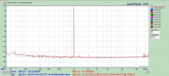
The SN7 is ridiculously better than a 12AU7. Try getting a 12AU7 to do this. Yes, this is SN7 at preamp levels. And damn near perfect. I can also show you the same exact tube operating at tens of volts, but it might confuse you having to look at two graphs. It has before.
As your rude and condescending posts continue to multiply at a number of different threads, I am beginning to think you have nothing real to measure, and nothing to measure it with. A whole lot of handwaving going on. Some of us actually build and measure.
Attachments
- Status
- This old topic is closed. If you want to reopen this topic, contact a moderator using the "Report Post" button.
- Home
- Amplifiers
- Tubes / Valves
- tube regulators