Hello,it´s time for some help again, Been working on this parafeed thing all day what I`ve come up with is that the gain is not enough to drive the Sewa to full output,I use 4:1 now.
The sound is a "littla"dark low treble and mid.If I put a condensator at "A" I get the treble amd mid´s again and a little more gain.If I put a condensator at "B" I get a lot of gain,all I need + the treble an mid´s.
But I wonder what effekt on the parafeed does this condensators have?It sounds god with them.Should I use a 1:1 trafos instead?
Unfortunately the introduction of the cap in either position is bypassing part of the expensive output transformer, it shouldn't be there - get rid of it.
The reason that it is effecting the balance of the sound is because it is only letting part of the signal through - but without the appropriate stepping ratio of the transformer.
Adjust the ratio of the output transformer to get the gain you want. It should perform well at 2:1 if you can get it to that.
That´s what I want..but the lowest I can get is 4:1,I will have to change the transformer...to bad..It should perform well at 2:1 if you can get it to that.
Hi Tyimo,
Simple one that works is based on the following stage input impedance, Zin in ohms and the lowest frequency you want passed in Hz (F3):
CuF = 1,000,000/(6.28 * Zin * F3)
Double the resulting cap value for good measure.
As long as it conducts, it can be pink polka dots")
Cheers!
Tyimo said:Hi Geek!
Could you help me to learn how to calculate the best value of the bypass caps ( HF decoupling near the anode) and the cathode caps???
Simple one that works is based on the following stage input impedance, Zin in ohms and the lowest frequency you want passed in Hz (F3):
CuF = 1,000,000/(6.28 * Zin * F3)
Double the resulting cap value for good measure.
Tyimo said:One more: I have 3mm generic yellow leds. Are they good for your tube preamp or I must use reds???
As long as it conducts, it can be pink polka dots
Cheers!
Hi Geek!
Thanks! I didn't understand why a 220uF ELKO was used in Stefano's 6N30 preamp for HF decoupling.....
Ahh, yes! I will looking for one!!
Greets:
Tyimo
Simple one that works is based on the following stage input impedance, Zin in ohms and the lowest frequency you want passed in Hz (F3):
Thanks! I didn't understand why a 220uF ELKO was used in Stefano's 6N30 preamp for HF decoupling.....
As long as it conducts, it can be pink polka dots
Ahh, yes! I will looking for one!!
Greets:
Tyimo
Different LED's have different voltage drops, so a bit of experimenting is in order. Modern LED's seem to all have a voltage drop of about 3.5V (even the RED ones) which makes them a bit less useful. Try to find old ones for the range of voltage drops you will need to fine tune your bias. Don't expect your bias point to be exactly the same as you get with plain unbypassed resistors - there is DC feedback involved.
Sounds like hum inducting into the output transformers from the power transformer. Try turning them or otherwise moving them further apart.
Shoog
One more on the parfeed,I get a little hum when using the parafeed,if I run it capacitor coupled theres no hum,any idea why??
Sounds like hum inducting into the output transformers from the power transformer. Try turning them or otherwise moving them further apart.
Shoog
I tried the Interstage with 1:1 and guess what NO humSounds like hum inducting into the output transformers from the power transformer. Try turning them or otherwise moving them further apart.
,at 8:1 there was quite alot hum,less at 4:1 and NO HUM at 1:1,strange or what?Shoog said:Different LED's have different voltage drops, so a bit of experimenting is in order.
Modern LED's seem to all have a voltage drop of about 3.5V
(even the RED ones
I am sure most understood this. That normal LED forward voltage is not 3.5V. This is value is for two diodes in series.
Gives like 1.70V --- 1.80V per LED.
The old RED ones has 1.55V --- 1.65.
This is at about 2-10 mA which I think is a normal current in most TUBES, too.
-----------------------------------------------
White LED and Blue LED
are different from red,orange,yellow, green.
Have got considerably higher voltage and are much more expensive, too.
White LED have typically like 3.0V --- 4.2V voltage drop across 1 LED.
I think is the same for Blue LED 3 - 4 Volt.
Different types of RED LED, sizes, shapes, light angles, even from same brand at same current,
can have very varying V-F drop.
Maybe +-15% from the average 1.75V ..... at 5 mA.
www.Everlight.com and www.Kingston.com are two big leading makers of all sorts of LEDs.
HP, Hewlett Packard has been and are also big when it comes to LEDs.
lineup
That normal LED forward voltage is not 3.5V.
I went through the whole of the Maplin catalogue last year and found practically all of the LED's to have a voltage drop of about 3.5V per diode. It seemed as though these were mostly high light output diodes - which may account for the high voltage drop. This applied to all colours !! In the end I used salvaged old ones.
All I would say is read the specs and don't take it for granted.
Shoog
Must have been very special LEDS.
There are many kinds.
Fact is: ( so nobody get mislead here ) ------------------------------
Nowadays,
most Standard 5mm LED has got VF 1.90-2.10 at 20mA.
But in audio and else we mostly use them at lower currents
than this.
And at current of 2-10mA, voltage is lower,
like I said average is 1.70-1.80 for new kinds, Red,Orange,Green,Yellow.
These are the most sold and so cheapest main stream LEDs.
--------------------------------------
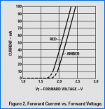
At http://uk.farnell.com/ this one is The Standard 5 mm RED LED
Datasheet:
http://www.farnell.com/datasheets/70661.pdf
Voltage forward drop / different diode current
-------------------------------------
Normally TWO Orange LED would give like 3.6 - 4.2 Volt at 10 mA.
And as I said earlier,
that 5687 Transistor Current Source, is targeted at 10 mA
and so would give a gate-cathode voltage of like 4.3 volt for tube.
Here is schematic with a ~9-10 mA Constant Current Source
and a 430 ohm cathode resistor:
http://www.diyaudio.com/forums/attachment.php?s=&postid=1052454&stamp=1163094193
lineup
There are many kinds.
Fact is: ( so nobody get mislead here ) ------------------------------
Nowadays,
most Standard 5mm LED has got VF 1.90-2.10 at 20mA.
But in audio and else we mostly use them at lower currents
than this.
And at current of 2-10mA, voltage is lower,
like I said average is 1.70-1.80 for new kinds, Red,Orange,Green,Yellow.
These are the most sold and so cheapest main stream LEDs.
--------------------------------------
At http://uk.farnell.com/ this one is The Standard 5 mm RED LED
Datasheet:
http://www.farnell.com/datasheets/70661.pdf
See my attachment for a diagram with curves:Product Detail
Order Code: 1003151
Part Number: HLMP-EG24-PS000
Description: LED, 5MM RED
Voltage forward drop / different diode current
-------------------------------------
Are you saying you aim for a Gate - Cathode voltage: -7 Volt .... ???Having just looked at the datasheet, my best guess on the operating point is that he is using a 150V on the plate with a bias point of about 6V for a current of about 20mA. That looks very good for what you want. The suggested 200V of B+ should work on this setup.
Two orange LED's should substite very nicely for the 430R cathode resistor.
Shoog
Normally TWO Orange LED would give like 3.6 - 4.2 Volt at 10 mA.
And as I said earlier,
that 5687 Transistor Current Source, is targeted at 10 mA
and so would give a gate-cathode voltage of like 4.3 volt for tube.
Here is schematic with a ~9-10 mA Constant Current Source
and a 430 ohm cathode resistor:
http://www.diyaudio.com/forums/attachment.php?s=&postid=1052454&stamp=1163094193
lineup
Attachments
Are you saying you aim for a Gate - Cathode voltage: -7 Volt .... ???
No, what I mean't was that when I tried to buy new LED's from Maplin thats what I found. I think I found only one or two in their range which were described as having less than 3V per diode. Believe this or not - its what I found. When I build mine I used 2 old orange LED's for a bias of about 4V, as you suggest.
Again all I am saying is check the specs and don't expect all LED's to perform in the way that they are described on this forum.
Shoog
Hi Tyimo,
I've run this as low as 125V on the anode of the top tube, so give it a go
The SRPP should balance automatically to B+/2 on the top tube's cathode, +10% or so. Each ECC88 section is fair linear down to around 50V across it.
Cheers!
Tyimo said:
Could I operate your preamp with +150Vdc?
I've run this as low as 125V on the anode of the top tube, so give it a go
The SRPP should balance automatically to B+/2 on the top tube's cathode, +10% or so. Each ECC88 section is fair linear down to around 50V across it.
Cheers!
The SRPP should balance automatically to B+/2 on the top tube's cathode, +10% or so. Each ECC88 section is fair linear down to around 50V across it.
Thanks Geek!!
PSU for SEWA tubepreamp
Hi!
Could somebody suggest me a good, but simple regulated +150V PSU with 6.3V heathers for my tubepreamp?
My trafo has 120Vac and 6.3Vac.
I thought on the original BOSOZ PSU with some minor upgrades. (higher voltage zeners)
Geek! Should I use AC filaments for your design, or I need DC this time, because the cathode is unbypassed and the heater induced hum would be unacceptable high??
BTW: what is better AC or DC or regulated DC filament????
Greets:
Tyimo
AC heaters are usually fine. I have never had hum issues with ECC88's and AC. The heater winding needs to be earthed though. I have needed to use DC on 5687 to get them hum free, so it depends on the valve. Always try AC first, and don't jump to the conclusion that hum is coming from the heaters, and it usually isn't.
Getting good DC from a 6.3V winding is no trivial matter and requires huge capacitance, and possibly an inductor.
Shoog
Getting good DC from a 6.3V winding is no trivial matter and requires huge capacitance, and possibly an inductor.
Shoog
- Status
- This old topic is closed. If you want to reopen this topic, contact a moderator using the "Report Post" button.
- Home
- Source & Line
- Analog Line Level
- Tube Pre Amplifier for SEWA 7 Watt ClassA MOSFET