Kooka said:
Hi Julien, your settings are based on the use of the 4 opamps board. Ok. Are the same settings valid for the 2 opamps board? I ask this because my default settings are different, in the 2 opamps board I am using.
As an example, my J6 and J7 sockets are not shortened as you say "default setting"...
Got it now, just did not check correctly: you are right about the default settings.
Julien_M said:Here are the settings for the digital input/re-clock/oversampling board. The SE DAC can operate in 4 different modes. I've tested all these 4 settings with my SE DAC and they all worked. The default setting on mine was 4x OS + re-clock. When the re-clock circuit is ON only 16bit/44.1MHz sources work well as this is a fixed clock.
NOS (no re-clock):
J3: open
J4: open
J6: open
J7: open
S3: all OFF
S7: all OFF
S8: all ON
S1: ON-OFF-ON-ON
NOS + re-clock:
J3: open
J4: open
J6: short
J7: short
S3: all OFF
S7: all OFF
S8: all ON
S1: OFF-OFF-ON-ON
4x OS (no re-clock):
J3: short
J4: open
J6: open
J7: open
S3: all ON
S7: all ON
S8: all OFF
S1: ON-OFF-ON-ON
4x OS + re-clock (default) :
J3: open
J4: short
J6: short
J7: short
S3: all ON
S7: all ON
S8: all OFF
S1: OFF-OFF-ON-ON
I'm attaching a picture of my input board in NOS mode for reference. That's how I have it now.
Julien, you say in NOS mode J3, J4, J6 and J7 should be open; then you show your board with all the J's shortened and you say it is in NOS mode....
There's something I am missing.
Kooka said:
Julien, you say in NOS mode J3, J4, J6 and J7 should be open; then you show your board with all the J's shortened and you say it is in NOS mode....
There's something I am missing.
They're open. I just left the jumpers hanging on one pin so I don't loose them.
It should work. If you think you'll stick with NOS you might want to remove the SAA7220 chip as it shares the same power supply as the clock and input receiver.
I just had a hour and a half listening session and I'm amazed by the ability of this DAC to resolve detail, yet it sounds very smooth and musical. It's really good. I think this op-amps are very good too, but I'll try different ones in the future, there are so many options...
I still have to play with all settings and hear what's best in my system...
hi Julien_M,
your message.
Another thing I did was to replace the 3 caps (C5, C6, and C8) at the digital input before the CS8414/CS8412 receiver with jumpers. These caps are not really needed since there's a transformer already. These are only to offer extra protection for the input chip against DC voltages (in case of an accident). Since there is no DC in an S/PDIF signal, they can be bypassed.
Hi Julien,
U can remove the protect DC caps. Bucause most Cd transport also had capacitor coupling( block the DC) for the Digital out.
If totally two caps between transport & DAC. probably will effect little of the sonic( by jitter). But I am not sure.
I use protect caps because I am not sure all the CDP or CD-Rom all had caps on te output tips( RCA ) to block the DC or not!
If U make sure that your transport had caps to block the DC. U can remove for it.
Julien, many thanks for your support!
thx
thomas
hi all,
I will prepare two new items.
1. DIR9001 digital receiver ( low jitter than 8414/8412 IS) to upgrade. performance will better than old 8414/8412-IS.
http://www.diyaudio.com/forums/showthread.php?threadid=110738
http://focus.tij.co.jp/jp/docs/prod/folders/print/dir9001.html
it will funish, test & can directly plug & use original 8414/8412-IS socket.
2. I will prepare Tube buffer PCB.
Diyers who bought kit with tube buffer will free to get one. But need to pay postage!
thx
thomas
tube-lover said:hi all,
I will prepare two new items.
1. DIR9001 digital receiver ( low jitter than 8414/8412 IS) to upgrade. performance will better than old 8414/8412-IS.
2. I will prepare Tube buffer PCB.
Diyers who bought kit with tube buffer will free to get one. But need to pay postage!
thx
thomas
Hi Thomas, I am in the list for the tube buffer PCB's (I bought 2 tube buffers, as you maybe remember, so I will need 2 PCBs), please let me know how much I should send you (BTW, if you still did not send the MKP caps you promised, you could send together).
Thanks, please let me now, my friend.
hi kooka,
ok, two pcs PCB. U not need to pay PCB money to me.
only postage will enough.
this is offer to tube buffer buyers.
Kokka,
do know recently what I was doing???
I broken Kondo Ongaku ( for clone one to diyers).
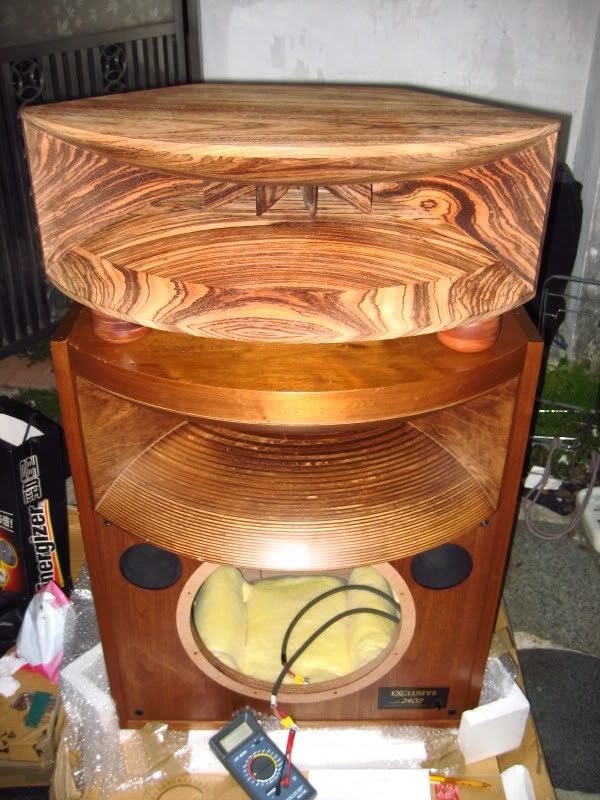
Broken TAD exclusive 2402. USE 4001 horn driver, 1601a Alnioc woofer, 4001 horn mouth * cabinet. mainly was crossover.
I broken them to colect data already.
I will clone & test with original one.
thx
thomas
ok, two pcs PCB. U not need to pay PCB money to me.
only postage will enough.
this is offer to tube buffer buyers.
Kokka,
do know recently what I was doing???
I broken Kondo Ongaku ( for clone one to diyers).
Broken TAD exclusive 2402. USE 4001 horn driver, 1601a Alnioc woofer, 4001 horn mouth * cabinet. mainly was crossover.
I broken them to colect data already.
I will clone & test with original one.
thx
thomas
An externally hosted image should be here but it was not working when we last tested it.
tube-lover said:hi kooka,
ok, two pcs PCB. U not need to pay PCB money to me.
only postage will enough.
this is offer to tube buffer buyers.
thx
thomas
Ok Thomas, just let me know when you will have them ready and how much is for shipping.
hi ggta,
your message.
have a full balanced kit version. For test I would like to use it in single ended mode. Is it possible to do so if I plug the "-" to the ground at the output of the I/V ?
.
can U share? in my set up. Balance better than SE.
But, if finally U like the SE version. remove the CPLD chips( module)
Remove one 1541a , se one OP-amp output will be OK.
op-amp output board. U will see L-E-R
E connect to two channel ground will OK.
thx'
thomas
tube-lover said:
Broken TAD exclusive 2402. USE 4001 horn driver, 1601a Alnioc woofer, 4001 horn mouth * cabinet. mainly was crossover.
I broken them to colect data already.
I will clone & test with original one.
thx
thomas
An externally hosted image should be here but it was not working when we last tested it.

Can you get 2nd hand TAD driver in HK? The new TAD are too expensive for DIY.
btw, did you saw this post. Is this what you planning to do?
http://www.diyaudio.com/forums/showthread.php?threadid=80068
hi samL,
done already.
now is clone the TH-4001 horn mouth ( use Canada maple Plywood ) Curve was according real TAd TH-4001 & clone for it.
In Hong Kong TAD 4001 still expensive. probably U can try to search in ebay. I can prepare Horn mouth for U, crossover too.
take a look for the broken 2402 & another A290 Solid fine ebony Horn mouth! THis horn mouth use C37 similar treatment & compare to original TH-4001.
mainly was crossover. I will considerate prepare Bitch plywood cabinet + maple Plywood TH-4001( clone ) horn mouth. probably 1601a or b I can get in hong kong. But still not cheap. but if post together will less postage!
see the photos, U will surprise.
what i do.
thx
thomas
Kooka said:
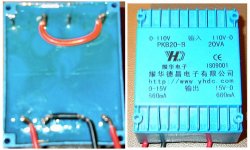
This is about the 18V transformer, and it is related to 220/240V countries (NOT for 110/120V ones!)
On the left the primaries: pins 1 and 3 (top to bottom) bridged. Pins 2 and 4 to mains.
On the right the secondaries: pin 1 to one 16V socket, pins 2 and 3 (together!) to the 0"" socket, pin 4 to the other 16V socket.
Of course this is if you have my same transformer, and of course you will have to check with a multimeter, having 16V (actually you will find about 118/20V) between pin 1 and 2/3 and between pin 4 and 2/3.
Hope this helps.
Hi Kooka,
I about to finish wire up my 15V transformer for 220V main. Before I connect to the main, just need to make sure both our transformer are a like and I have done it correctly.
Attachments
Ops! I did get it wrong as the numbering on the transformer are not sequential. The diagrams on this web site will answer it all.
http://solderman.blogspot.com/2005/09/transformers-series-and-parallel.html
http://solderman.blogspot.com/2005/09/transformers-series-and-parallel.html
Well, I wire up the transformers, did a measurement to make sure it is working. Connect it to the PCB (with no source input), the red LED did not light up. Not sure what I have done wrongly.
The 15V transformer reading before connected to PCB. 15.9V (red) , 13V (black) and 15.87V (red). The 9V transformer reading before connected to PCB. 13.96V (red), 12.4V (black).
The 15V transformer reading before connected to PCB. 15.9V (red) , 13V (black) and 15.87V (red). The 9V transformer reading before connected to PCB. 13.96V (red), 12.4V (black).
Attachments
- Status
- This old topic is closed. If you want to reopen this topic, contact a moderator using the "Report Post" button.
- Home
- Source & Line
- Digital Source
- Tube-lover SE and Full Balance TDA1541a DAC