even so, you can still use that jensen iso traffo, you can choose the best location, before or after the tvc, try it both ways and see which position you like best...
the galvanic isolation alone is worth a try...
or you can use SY's heretic line stage....
A Heretical Unity Gain Line Stage part II
I can't play with the hi-fi now (it's too late at night) but I need to get out some clip leads and see if the transformers will at least work without loading anything down too much. The galvanic isolation would actually break a pesky ground loop I've been battling.
SY's Heretical Preamp would be good, yes. Unfortunately it doesn't have balanced output, which I was hoping to get out of this. But I don't actually *need* balanced connections. I just want them. Hence all the talk of LTPs and cathodynes.
--
so why not just use a cinemag or a jensen 1:1 traffo?
Because you may still need some gain.Good question!
")
Isn't that circuit from the Jensen app note just adapting the unbalanced signal to the balanced output? It looks like there will be gain from Pin 2 on the output XLR, but no gain from Pin 3.
This is not a requirement for a balanced cable interface.
Because you may still need some gain.
That's a good point, but in this case I actually don't need any gain. But I would like to add just a little 'tube warmth.' Gain of 5x or 6x will still work, since the speakers have selectable -10dBV or +4dBm sensitivity.
I already have a dumbed down version of the Impasse working. I like the sound of it, but it has too much gain and there's a little bit of hum which I'd like to get rid of. I read in MerlinB's High Fidelity Tube Preamp book that the cathodyne is not a good choice for a phase splitter/cable driver since the plate (anode) has poorer PSRR than the cathode, causing common mode rejection to not work well (hum level is different on inverted output than on non-inverted output, so they don't cancel). Since common mode noise rejection is a major reason for using balanced operation, I was thinking an LTP stage would be better in this case. Then came talk of transformers for phase splitting, which are noiseless, but then no tube warmth. Maybe 'transformer warmth'? I guess I'll know when I try it...
--
Last edited:
Broskie already sorted out all the issues you mention in the converter, so check out his blog.
I went looking for his unbalanced to balanced converter. There's no PCB for that on his Glassware site, but maybe you're thinking of this?
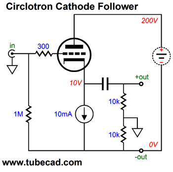
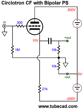
Circlotron—Once Again
So, try something like this?
Or this?
--
Or were you thinking of the Aikido SE-to-Balanced circuit?
Aikido Single-Ended-to-Balanced Topology
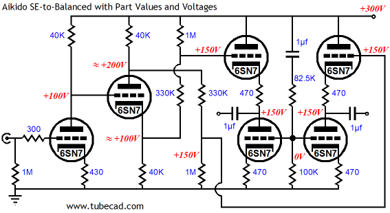
SIX twin-triodes for a stereo line stage?
--
Aikido Single-Ended-to-Balanced Topology
SIX twin-triodes for a stereo line stage?
--
Last edited:
I was just reading this old thread, back from when I first built this Impasse-style preamp.
Unbalanced In > Balanced Out line amp - How To Do It?
It seems I forgot a lot of those lessons learned. Time re-learn them.
--
Unbalanced In > Balanced Out line amp - How To Do It?
It seems I forgot a lot of those lessons learned. Time re-learn them.
--
I just bought an Impasse pcb, and I'm still planning on trying that, but would an LTP with MOSFET source follower outputs be better for this particular application? I'm thinking a 6N6P LTP with 10k plate loads and a CCS in the tail, DC coupled to something simple like IRFBC20 MOSFETs, would work well.
yes, this seems like a good plan, and if using IRFBC20 MOSFETs looks like a simple and yet effective, and you have an option of balanced /unbalanced inputs with balanced outputs,
since you got this in your first post, i suggest that you do this and find out...
the 6FQ7 seems good for the ltp, or you may want to try the 6GU7, a tad lower mu...
I did some LTspice simulations last night, and the LTP with MOSFET source followers looks far better than any other option. You get the lowest THD and the most output swing, no matter which triode you use. There are several twin-triodes with mu of 15 to 20. All look very good in simulations.
I took the measurements from the pair of 10k:600 Edcor transformers I have, made a quick model, and did a simulation with various single-ended triodes driving them. I compared the various circuits with 1V RMS output on each output (which would be 2V RMS differential). The THD from the LTP and source followers is down around 0.01% at that level, and all 2nd harmonic, which will cancel in push-pull. The THD from any triode into the 10k:600 OPT is up around 0.1% (I tried 6DJ8, 12HL7, 5687, 6N30P), with some 3rd harmonic (which won't cancel out) along with the 2nd. I tried parafeed too, and the THD is basically the same.
So yes, the LTP w/ source followers wins in the distortion department.
PS - Edcor XSM10K600 measurements:
Pri L = 22H, DCR = 465R. Sec L = 2H, DCR = 120R.
I guessed at the LTspice coupling, putting in 0.9998. That gave a high frequency pole of about -3dB at 35kHz.
Re: Shef's suggestion -- That's interesting. Basically use a line level version of this headphone amp:
DIY 6DJ8 (ECC88) Tube Hi-Fi Headphone Amplifier Project
Will need a negative supply for the tail, of course.
Last edited:
Cascode the source followers?
Or cascode the CCS under the LTP?
Anywhere. Really. Especially the source followers.
cheers,
Douglas
With 7V on the cathodes' CCS not really, IMO.Re: Shef's suggestion -- That's interesting. Basically use a line level version of this headphone amp:
DIY 6DJ8 (ECC88) Tube Hi-Fi Headphone Amplifier Project
Will need a negative supply for the tail, of course.
If to make that CCS efficient from down to 0.6-0.7 == all to the minimum possible (correct me if I misunderstand smth) then 7V is fine without the negative rail. Versus e.g. CCS on LM317 where its "minimum efficiency voltage" is 1.25V + some 317's drop, that's what I figured from experimenting.
That 0.6-0.7 could be achieved with CCS path consisting of a single transistor, which could be controlled by the network fed from B+ or the additional LV source.
I think the Lundahl LL1922 4 + 4 : 1 + 1 will work perfectly for your goal. Unlike, for mine I need it opposite and at least 1 + 1 : 4 + 4 as suggested by Bandersnatch, which seems be the tough load for the 6SN7 LTP. I ordered some trafos for testing, hopefully it will work for driving either fixed-biased or the MOSFET output stage.
Last edited:
why is it that in the RCA tube manuals for RC coupled voltage amps,voltage gains are no more than tube mu?
RC coupled !! Resistance Coupled!
We have to get DC power into the tube.
The cheap (and wide-band) way to do this is with a 12 cent resistor.
The tube is a resistor too. Its output is limited by its plate resistance.
The plate resistance and the external resistOR (and any load) divide-up the Mu.
As a simple case, we can make RP = rp and get half of Mu. This approximates maximum "power" transfer (it is always a power problem, even when we say voltage amplifier). This is about where 12AX7 are run, and give gain of about 50.
When rp is much lower than our load, we make RP||load 2X to 5X higher than rp and get 2/3 or 3/4 of Mu. 12AU7 in audio often gives gain near 15.
Resistor loading is not the only way.
A GOOD transformer presents an "infinite" audio impedance and gain to plate is very nearly Mu. (However practical transformers tend to fall short of "infinite" impedance, especially over the hi-fi band.)
A Pentode (or FET) worked with fixed voltages above the knee is, not infinite, but very-very high dynamic resistance compared to its DC resistance. You can also use current NFB and any active (capable of gain) device be "pretty infinite". However +adding+ a device just to reach a gain of Mu of the first device leaves a lot of gain on the table. A 12AX7 with a 6AU6 load and infinite external load may reach gain of 99, true. But 12AX7 feeding 6AU6 gain-stage should give gain of 50*100= 5,000! If that is too much(!), and your religion is not offended, you can apply NFB and get exactly the gain you want (not just the Mus available in tubes). And since there is always an external load, you need a third device to buffer it. Now we have three devices and can make a "nearly perfect" amp, no matter what the Mus really are. Precision is gained, simplicity lost....
- Status
- This old topic is closed. If you want to reopen this topic, contact a moderator using the "Report Post" button.
- Home
- Amplifiers
- Tubes / Valves
- Tube line stage with unbalanced input, balanced outputs?