i did not know that triode voltage amps can have voltage gains higher than the tube mu,
since rp is fixed at operating point, even an infinite resistance load in parallel with it only gives a load approaching rp, that was how i understood...what did i miss....?
the second stage which is a concertina is supposed to give a gain of approx. 1, am i wrong there too?
i read the Allan Kimmel article and he said his mu follower can approach the mu of the tube, hence the mu follower, Allan even have a balanced mu follower, that can be used
as a fully balanced tube line amp...
SY's Impasse can be a balanced input owing to the input transformer it used....
but i guess you are the expert on this Kevin....
rp appears in series with an infinite (or near infinite) load resistance not parallel represented by the CCS, your normal plate load resistor is not present in this instance. The near infinite load impedance of the next stage appears in parallel with RL. rp is an internal parameter of the tube, nothing appears in parallel with it.
So as an example think about what sort of voltage division occurs if a source impedance of 8K (your 6SN7) is driving an AC load impedance of 1 Mohms? Remember that the next stage being driven ignoring the very small amount of miller and stray capacitances is also extremely high impedance. A good CCS should achieve impedances of several Mohm at audio frequencies. (My example may be extreme.) The resulting loss is -0.069dB with a CCS achieving 1M equivalent AC resistance so the gain resulting from a mu of 20 which is 26dB is reduced to approximately 25.931dB, so in a sense you are right, but the difference is small enough it does not really matter.
Note that the lower the rp of the tube the better this works, and in the real world you will get almost exactly mu for voltage gain.
Note that my comments do not apply necessarily in the case where there is a resistive divider between the two stages as this both reduces the gain of the preceding stage by loading it down, in the Impasse the 1.68M load (R8, R9) will have result in some additional loss say 0.04dB, but attenuates the signal by slightly less than 3dB at the grid of the concertina output so actual gain is about 29dB as opposed the 32dB I previously stated. (Remember that since the signal on the grid appears at both the plate and the cathode and is more or less the same voltage level as that appearing at the grid which is where the additional 6dB of gain comes from)
The concertina has a gain approaching 2 if you look at the output differentially, a cathode follower has a gain approaching 1.
I hope I have not explained this so badly that I have added further to the confusion.
Consider something like a 5687 driving a phase splitting transformer. With this setup you get galvanic isolation. The 5687 has better drive capabilities than the 6DJ8. However something like the ECC99 might even be better and then you could consider a bit of a step down to gain some extra drive capabilities.
Shoog
I have some 5687 tubes to use for this. What kind of output transformer would be best for this? Something with an air gap? Or use parafeed? Also, what kind of stepdown? Would a 2:1 stepdown be about right? The higher the stepdown ratio, the more gain required of the tube, and the higher the harmonic distortion at a given output level, correct?
rp appears in series with an infinite (or near infinite) load resistance not parallel represented by the CCS, your normal plate load resistor is not present in this instance. The near infinite load impedance of the next stage appears in parallel with RL. rp is an internal parameter of the tube, nothing appears in parallel with it.
this is the first time for me to hear about this tbh....
all the while i thought that there was no escaping rp and that Rl and next stage Rg or grid leak resistors are all in parallel....
i may need further convincing...
I see a further complication...err, feature. Take a SE stage, and feed a concertina. Use a parafeed, 2:1+1 output TX to carry the signal. I am thinking that any mismatch in loading of the two '1' stages will be carried by both the plate and cathode equally and therefore leave the concertina stage with cathode follower output Z overall. A good thing imo...
I like the LTP topology, its PSRR is certainly higher than the concertina stage and the same parafeed output can be applied to it.
cheers,
Douglas
I like the LTP topology, its PSRR is certainly higher than the concertina stage and the same parafeed output can be applied to it.
cheers,
Douglas
I wouldn't go parafeed as it adds complexity and the parafeed cap would have to be quite large to avoid resonant spikes in the bass region - think at least 8uf to be on the safe side.I have some 5687 tubes to use for this. What kind of output transformer would be best for this? Something with an air gap? Or use parafeed? Also, what kind of stepdown? Would a 2:1 stepdown be about right? The higher the stepdown ratio, the more gain required of the tube, and the higher the harmonic distortion at a given output level, correct?
That leaves you with a gapped OT which are not exactly plentiful in the preamp range. I think Lundhal and Sowter would be good places to start looking. I would go for a 2:1+1 which will give a predictable plate load but take some of the burden off the OT. If you don't need the gain then 3 or 4 to 1+1 would be better. Its going to be a trade off between increased gain derived Harmonic distortion vs increased harmonic distortion created by the lower load - only experimenting would find the sweet spot.
In any reasonable setup the 5687 should have gain to burn though.
Of course another approach which will be cheaper in the end, and possibly perform better, is to use an input phase splitting transformer to feed a LTP with a stiff CCS tail. Take the outputs off the plate for a reasonable output impedance or follow with a step down OT which only needs a minimal air gap. The demand on the input transformer is much lower than any OT and so can be cheaper and smaller. You can stick with a 1:1+1 ratio or even a 1+1 input choke. The benefit is that the LTP will realise twice the gain of a single input version at minimal extra complexity I fairly much predict that this wil perform better than the other alternative. If you use a Blumheim Garter bias arrangement on the 5687 you can use a none gapped OT if you decide you need/want one.
Shoog
Last edited:
Since the OP has powered speakers, the Impasse seems to be ill-matched - it was designed to drive near-unity gain PA's. Check out TubeCAD's Aikido-based unbalanced to balanced buffer/converter, which takes care of the potential plate-cathode output imbalance as well as the PSRR.
p.s. there is no such thing as the Blumheim<sic>, or the Blumlein garter bias, as it was debunked in this forum not long ago.
p.s. there is no such thing as the Blumheim<sic>, or the Blumlein garter bias, as it was debunked in this forum not long ago.
this is the first time for me to hear about this tbh....
all the while i thought that there was no escaping rp and that Rl and next stage Rg or grid leak resistors are all in parallel....
i may need further convincing...
rp and RL are not in parallel, they are in series. RL and RI are in parallel, with a CCS the value of RL can be extremely large making it essentially irrelevant in the case of a tube with modest rp, then only RI is relevant if it exists.
Learning to do simulation would allow you to understand easily or do some bench measurements of a triode loaded by a CCS and you will see what I am talking about. (Just be sure to use a 10X probe so you don't load down the output significantly)
I can get almost exactly 60dB gain (actually measured) with a two tube circuit using CCS mu-followers with one tube having a mu of 20 and the other having a mu of 50.
... ... ... ... ... ... ... ... ...
I hope I have not explained this so badly that I have added further to the confusion.
Good accurate summary.
Yes, cathodyne has gain of 2. When taken differentially, which is almost always why we invited it in. (Instant exception is the phase-shifter, which only has one unity-gain output.)
Triode with *infinite* load gives gain very near Mu. Looking broadly: any approximation to "infinity" generally requires insane supply voltage, or excellent choke/transformer, or additional active devices to feed and buffer. When dumping parts (money) into a plan, you should ask if there is a better way to deploy these parts. For example one plan mentioned here has 4+ transistors. That's more than enough to build a VERY accurate low gain amplifier... so why is the tube here? If we lock-in the tube with transistor feeding and buffering, is it really a "tube" or a slave to the circuit, a $200 decorative spacer? I do not know the answers.
Thank you for confirming my remarks, I had the distinct feeling I wasn't getting through..
For decades I avoided mixing solid state and tubes because I didn't like the result. Have to say that the cascode depletion mode mosfet ccs/mu-follower at least implemented with the Supertex DN2540 is quite transparent and not solid state sounding in the pejorative sense. You get mu, and very low distortion as well.
Ixys and Supertex (Microchip subsidiary now) make some very interesting depletion mode devices. I am now using a mix of jfets (Linear systems), depletion mode mosfets and tubes in my latest designs. I was hesitant but am pleased with the results so far. Next project uses triode connected D3A and Ixys mosfet based cascode mu-follower to drive 300Bs, that will be my first foray into large signal with hybrid circuitry. In the past I used chokes, transformers, SRPP and traditional RC coupled drivers in my designs, so this is a vote of confidence since the amps in question are for personal use and are expensive.
...Of course another approach which will be cheaper in the end, and possibly perform better, is to use an input phase splitting transformer to feed a LTP with a stiff CCS tail. Take the outputs off the plate for a reasonable output impedance or follow with a step down OT which only needs a minimal air gap. The demand on the input transformer is much lower than any OT and so can be cheaper and smaller. You can stick with a 1:1+1 ratio or even a 1+1 input choke. The benefit is that the LTP will realise twice the gain of a single input version at minimal extra complexity I fairly much predict that this wil perform better than the other alternative...
I have a couple of different 1:1 non-gapped (I think) transformers that could be configured as input transformers. I have a pair of Edcor 10k:15k WSM series open-frame xfmrs, and a pair of Jensen JP-114-1 (1:1.4). Now come the questions...
1) I can turn the transformers around, right? For instance, use the 15k secondary on the Edcor trannie as the primary, to make it a 15k:10k.
2) I use, and am very happy with, one of Dave Slagle's autoformer volume controls. If used in this setup, I'd need to connect the input selector box to the autoformer volume control (AVC), then the output from the AVC to the input transformer primary, then the input transformer secondary would feed the two grids of the 5687 LTP.
Can the output from the AVC connect to the input transformer primary without adverse interactions? I think the AVC inductance is very high, something like 300H. The primary inductance of the Edcor WSM is only about 15H. What could I expect from such a combination?
3) Since I don't need any gain, wouldn't an LTP with unbalanced input fed to the grid of the first triode work well enough at these signal levels? I figure a 5687 LTP with a negative supply and a DN2540 CCS for its cathode load could do the phase splitting. The question is whether it would load down into the low 10k input impedance of these active speakers.
From what I've read, the output impedance from the plates of a 5687 LTP should be no higher than about 3k ohms (probably lower). That's roughly 1/3 the input impedance of the active speakers. I was originally thinking of DC coupling to IRFBC20 source followers to lower the output impedance and unload the 5687 plates.
I could also use a pair of center-tapped chokes (autoformers?) as plate loads for the 5687 LTP. But that only lowers the output impedance of the LTP a little bit, right? And within a more limited bandwidth, too.
The other possibility would be to use low-mu triodes with very low rp, perhaps an LTP made of two 12B4A per channel. The output impedance would be in the vicinity of 1.5k (I think) and the gain would be roughly 5X. I think I have enough 12B4A tubes on hand. Perhaps 12B4A LTPs with center-tapped chokes as plate loads? Hmmm....
--
Good accurate summary.
Yes, cathodyne has gain of 2. When taken differentially, which is almost always why we invited it in. (Instant exception is the phase-shifter, which only has one unity-gain output.)
Triode with *infinite* load gives gain very near Mu. Looking broadly: any approximation to "infinity" generally requires insane supply voltage, or excellent choke/transformer, or additional active devices to feed and buffer. When dumping parts (money) into a plan, you should ask if there is a better way to deploy these parts. For example one plan mentioned here has 4+ transistors. That's more than enough to build a VERY accurate low gain amplifier... so why is the tube here? If we lock-in the tube with transistor feeding and buffering, is it really a "tube" or a slave to the circuit, a $200 decorative spacer? I do not know the answers.
why is it that in the RCA tube manuals for RC coupled voltage amps,voltage gains are no more than tube mu?
Sure can!1) I can turn the transformers around, right? For instance, use the 15k secondary on the Edcor trannie as the primary, to make it a 15k:10k.
You don't actually need a transformer in front of a long tail pair, and I would suggest not using one for what you want to do.2) I use, and am very happy with, one of Dave Slagle's autoformer volume controls. If used in this setup, I'd need to connect the input selector box to the autoformer volume control (AVC), then the output from the AVC to the input transformer primary, then the input transformer secondary would feed the two grids of the 5687 LTP.
This is where an output transformer can help a ton.3) Since I don't need any gain, wouldn't an LTP with unbalanced input fed to the grid of the first triode work well enough at these signal levels? I figure a 5687 LTP with a negative supply and a DN2540 CCS for its cathode load could do the phase splitting. The question is whether it would load down into the low 10k input impedance of these active speakers.
Sure, source followers are a nice idea. At that point you won't need any transformers at all.From what I've read, the output impedance from the plates of a 5687 LTP should be no higher than about 3k ohms (probably lower). That's roughly 1/3 the input impedance of the active speakers. I was originally thinking of DC coupling to IRFBC20 source followers to lower the output impedance and unload the 5687 plates.
I wouldn't recommend this. Focus on what's under the connected cathodes, not what's loading the plates.I could also use a pair of center-tapped chokes (autoformers?) as plate loads for the 5687 LTP.
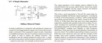
Here's something else to consider from Jensen Transformer's Application Notes #3. Posting this is like grinding sand in the eyes of certain manufacturers, but this frees you up to do just about whatever you'd like. (Also, I've used this and it works just fine!)
Attachments
why is it that in the RCA tube manuals for RC coupled voltage amps,voltage gains are no more than tube mu?
No one has claimed gains greater than mu from a single triode stage.
Since the OP has powered speakers, the Impasse seems to be ill-matched - it was designed to drive near-unity gain PA's. Check out TubeCAD's Aikido-based unbalanced to balanced buffer/converter, which takes care of the potential plate-cathode output imbalance as well as the PSRR.
p.s. there is no such thing as the Blumheim<sic>, or the Blumlein garter bias, as it was debunked in this forum not long ago.
so why not just use a cinemag or a jensen 1:1 traffo?
why not just use a cinemag or a jensen 1:1 traffo?
Good question!
One (self-inflicted) problem is that I use one of Dave Slagle's autotransformer volume controls (AVC). That's supposed to have 300H inductance. My setup has a 'passive preamp' kind of thing, with a Niles Audio input selector box, with interconnects to the Slagle AVC. The output from the AVC would then go to the primary of the 1:1 transformer. Would that be a problem?
Incidentally, I do have a Jensen JT-114-1 waiting in the wings. I'd be glad to use it for this.
Perhaps I could put buffers after the volume control, before the primary of the 1:1 transformer. I guess a single 5687 or something with each triode wired as a cathode follower. I could use a bi-polar power supply so the grids could be at ground potential, eliminating a capacitor.
Last edited:
even so, you can still use that jensen iso traffo, you can choose the best location, before or after the tvc, try it both ways and see which position you like best...
the galvanic isolation alone is worth a try...
or you can use SY's heretic line stage....
A Heretical Unity Gain Line Stage part II
the galvanic isolation alone is worth a try...
or you can use SY's heretic line stage....
A Heretical Unity Gain Line Stage part II
my question remains why is that?
There is a mathematical relationship between transconductance and plate resistance that results in essentially constant mu over a wide range of operating points. As transconductance increases rp will decrease proportionately, and vice versa, transconductance is a function current through the device. (increasing transconductance with increasing current)
mu = gm x rp at a fixed plate current.
Change the plate current and both gm and rp change, one in inverse proportion to the other.
In a conventional triode mu can in a practical sense be treated as a constant. Note this is not true for triodes designed specifically for a variable mu characteristic. (usually for rf amplifier use)
There is a whole lot more right here on the forum:
tube basics: computing mu and transconductance
- Status
- This old topic is closed. If you want to reopen this topic, contact a moderator using the "Report Post" button.
- Home
- Amplifiers
- Tubes / Valves
- Tube line stage with unbalanced input, balanced outputs?