I've been thinking for a while of a hybrid vacuum/sand state integrated amp that would use several concepts I've been tinkering with and would run off of a power transformer from a plundered Scott/Fisher receiver (not that hard to find on E-pay).
There are three functional blocks involved - an RIAA amp, a line amp, and a power amplifier stage. The RIAA amp and line amp would suffer from the most nasty sand-state pollution. The power amp will be a Schade-feedback SE amp using fairly readily available triode-pentode noval tubes and a 6L6GC output stage (I wanted to use a screen driven output stage, but the sweep tubes with good power dissipation are too filament-hungry). For output iron, I have in mind the budget Transcendar 10W, 5k SE output transformers (have iron, will travel).
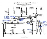
Attached is the initial concept schematic for the RIAA block, slated to drive a 100k volume pot of some sort.
There are three functional blocks involved - an RIAA amp, a line amp, and a power amplifier stage. The RIAA amp and line amp would suffer from the most nasty sand-state pollution. The power amp will be a Schade-feedback SE amp using fairly readily available triode-pentode noval tubes and a 6L6GC output stage (I wanted to use a screen driven output stage, but the sweep tubes with good power dissipation are too filament-hungry). For output iron, I have in mind the budget Transcendar 10W, 5k SE output transformers (have iron, will travel).
Attached is the initial concept schematic for the RIAA block, slated to drive a 100k volume pot of some sort.
Attachments
Last edited:
As connection to some sort of recording device is possible, I suggest you add 1 more "sand grain" to the phono section. Buffer the phono section with a ZVN0545A source follower. FWIW, I was successful in tweaking the "classic" RCA setup, with a ZVN0545A source follower.
Attachments
That depends on where the "out" is in the scheme of things. I have in mind an extremely hefty line amp stage that may be between the RIAA amp and the outside world. A more insular view might relegate the RIAA amp totally to "inside" duty, which would also be totally valid. Don't assume I'm not on top of all these distinctions, because I am.... This is an integrated amp after all, not an isolated RIAA stage - one block at a time...
Here's the first cut of the line amp. I may use a P-channel mosfet and a single green LED instead of the HV PNP at the output - I may try both. I'm probably going to use point-to-point wiring under the chassis with chunks of circuitry where necessary on perf board, which should make changes easier. What I'm doing isn't complex enough to justify a PCB.
Attachments
Here's the power amp. Some of the values are EWAGs/placeholders until I can get the thing up and tinker with it some. The input tube will remain secret until 1) I get my own stash at a decent price 2) I'm sure this thing is working right with my tube of choice. Having said that, there are a fair number of inexpensive triode/pentode pairs that would work OK in this application with a little bias tinkering. The venerable 6U8 would work more or less ok, but that's not the one I plan to use. Just to cull the herd a bit (lord knows there's tons of triode-pentodes out there), I'll tell you I'm selecting a tube with a medium mu, relatively high transconductance triode half. Of course you could also just use separate triodes and pentodes of your choice, but I'm trying to do this project using as few envelopes as possible.
I chose to use fixed bias but initially not regulate the bias and screen supplies. This was done in order to save parts. I may regulate these supplies in case this dodge does not give me a stable enough bias point.
I plan to power this setup with an old transformer from a Fisher receiver (It's either a 500B xfmr or a 400, I'd have to check). The tubes were chosen to work within the capabilities of the filament supply, otherwise I would have used screen driven sweep tubes in the output stage of the power amp (cheaper than the 6L6GC by a long shot).
Attachments
Last edited:
The input tube will remain secret until......
I know how that goes....I mentioned the 6EZ5 and before I got some....poof they went from $1 each to $4 or $5. I made a spreadsheet that I use for tube selection. I don't even list a tube with the same pinout that you show.
I would have used screen driven sweep tubes in the output stage of the power amp
I don't know how much reserve you have on the heater supply, but the 6GB5 is an excellent small sweep tube that needs 1.38 amps VS the 6L6GC's 0.9 amps. I already got 100 13GB5's. They are off of one dollar list already.
The 6BQ6GA is a fat bottled sweep that needs 1.2 amps. I and at least one other builder have ran them in the SSE amp. The 6DQ6 is also only 1.2 amps but I could never get that one to work well in SE. Didn't try screen drive though. Both have a compatible pinout with the 6L6GC if you wire a plate cap to pin 3. I added a pin jack so that I can plug in the plate wire if needed.
I have a way of checking the inventory at ESRC. I will not use a tube that is in short supply. In fact I just sold Stan $400 worth of tubes that I had saved for projects. These TV tubes got sucked into the spud SE vortex years ago by Bottlehead and others. They have been used up by audiophiles and become scarce and will vanish within a few years.
The reason I chose the 6L6GC was its decent plate dissipation with a reasonably modest filament draw. To get a similar plate dissipation with a sweep tube will cost me 2.5A per tube filament current.
As far as the basing on the input tube, it's that way 'cause it matched the tube that I want to use. I would have used the same tube for my phono preamp, but using the 17JK8 allows me to run the filaments with DC off the bias winding. Fisher used a similar scheme in their receivers.
As far as the basing on the input tube, it's that way 'cause it matched the tube that I want to use. I would have used the same tube for my phono preamp, but using the 17JK8 allows me to run the filaments with DC off the bias winding. Fisher used a similar scheme in their receivers.
I've noticed a power transformer on E-pray designed by Transcendar, with a winding suitable for ~400DC, a heavy, heavy filament winding, and a bias winding. What it lacked was capability for a 200V output for my preamp circuitry. The form factor was long and flat like the old Scott/Fisher receiver power transformers. If the 200V capability were present (a 140-0-140 winding with proper insulation) the design would work with screen driven sweep tubes. Maybe I should talk to G.G....
For many of my amps I have been using Antek toroids. Yes, they are ugly, but I hide them under the deck or inside a box.
For a small amp I use one of the 100VA sizes. Given the crest factor in audio they are good for a 100+ watt P-P amp in class AB. You can burn up to 60 watts of dissipation in Class A.
I wire two heater windings in series for 36 watts of heater power spread between 6.3 and 12.6 volt tubes.
I wire a bridge rectifier and cap to each HV winding to create two supplies, which I connect in series. This provides two voltage rails.
An AS-1T150 provides 200 and 400 volts. Good for class A amps.
An AS-1T175 provides 240 and 480 volts. Good for sweep tube P-P.
An AS-1T200 provides 275 and 550 volts. Good for sweep tube P-P with 6600 ohm OPT.
A pair of AS-2T230's should do for a mid sized amp, but they haven't been stocked since the fire.
For the really BIG amp I will use a pair of AN-64115's. A bridge on each 120 volt winding gives 4 X 160 volts which are all wired in series for 0-160-320-480-640 VDC. Total heater power is 180 watts. This monster is on my list for next year. It should do 300 to 500 WPC. I have all the hard parts.
For right now, the amp is getting built with Fisher power iron, since I have it. I also have the Transcendar outputs. I don't want to chase any more iron for this project at present. If I decide to do production on this or a variant of this design, that's another story.
Part of the exercise for this design was to get the functionality I wanted with a minimum number of tubes (cheap tubes!) but also within the capabilities of the Fisher power transformer. Constraints like that make the design interesting, and forced some choices that I think may have actually improved the design in the long run.
Part of the exercise for this design was to get the functionality I wanted with a minimum number of tubes (cheap tubes!) but also within the capabilities of the Fisher power transformer. Constraints like that make the design interesting, and forced some choices that I think may have actually improved the design in the long run.
For right now, the amp is getting built with Fisher power iron, since I have it.
I understand those constraints too. I will be moving everything in the next year or two......no more new transformers....repeat.....no more.....
I have given away or sold at least 1000 pounds of transformers and I still have at least that much left, including one or more each of all the small Anteks.
Part of the exercise for this design was to get the functionality I wanted with a minimum number of tubes
I am working on something like that too. I am waffling between 3 or 4 $1 tubes per channel, a $35 Antek power transformer, and some OPT's that I have plenty of, for a 30 WPC sweep tube amp. Idle dissipation must be kept low since it will be on almost continuously.
If I decide to do production on this or a variant of this design, that's another story.....Constraints like that make the design interesting
I try to think about what it would take for someone else to duplicate the design. That forces all sorts of design constraints, especially if you are thinking globally. Compactrons are a distinctly American phenomenon. This amp will use them anyway.
One other point - the low-slung Scott/Fisher power transformers nicely complement the low-slung Transcendar 10W output transformers. I may try some of Transcendar's push-pull iron for another project (similar low-slung look), in order to compare it to the vintage Scott/Fisher transformers I have on hand. So far, I haven't heard any report on the P-P Transcendars.
I have never heard anything but good reports so far. I have a bunch of the SE transformers. One pair is in an experimental jfet/mosfet HV cascode amp (yet to be perfected), and another set is going into this project. The look and feel is better that the Hammonds (better paint job, teflon leads vs. PVC), and the price on par with the Edcors.
As usual, as my projects progress in fits and starts (often displaced by other projects) I get other ideas that supersede the original intent. The line amp architecture has remained pretty much stable, except it now has gain and uses a mosfet rather than a bipolar device at the output.
The RIAA amp has morphed completely into a feedback-based confection designed around the 6N3P with sand helpers. No worries about output impedance now...
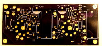
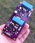
PCBs are laid out for both designs - I just got the reference designators sorted out this afternoon, as both designs were laid out free-hand without netting from a coupled schematic. I'll feed them to OSH Park when I'm ready, and get back some lurid purple boards for prototyping.
The RIAA amp has morphed completely into a feedback-based confection designed around the 6N3P with sand helpers. No worries about output impedance now...
PCBs are laid out for both designs - I just got the reference designators sorted out this afternoon, as both designs were laid out free-hand without netting from a coupled schematic. I'll feed them to OSH Park when I'm ready, and get back some lurid purple boards for prototyping.
Christmas Came Early
I wan't expecting this board to come in today, but I was pleasantly surprised. This is the line amp, the first functional block I'm building for the integrated amp. I've changed tubes, but the concept remains similar to the schematics I've presented here so far (a few refinements, though). I'll be building this up over the holidays. Tube sockets are on the bottom side, so the boards will be flipped over when finished, with all the topside components hanging down inside the chassis.
I wan't expecting this board to come in today, but I was pleasantly surprised. This is the line amp, the first functional block I'm building for the integrated amp. I've changed tubes, but the concept remains similar to the schematics I've presented here so far (a few refinements, though). I'll be building this up over the holidays. Tube sockets are on the bottom side, so the boards will be flipped over when finished, with all the topside components hanging down inside the chassis.
Attachments
Last edited:
- Status
- This old topic is closed. If you want to reopen this topic, contact a moderator using the "Report Post" button.
- Home
- Amplifiers
- Tubes / Valves
- Tube Integrated Amp