I was stymied at the workbench a couple of times today by silly things like not having a SATA cable on hand (to set up an old Windows PC for frequency response measurements), so in frustration I moved to the computer, and spent a little more time tinkering with LTSpice and KMG's LND150-based 12AX7 triode emulator.
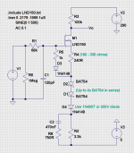
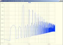
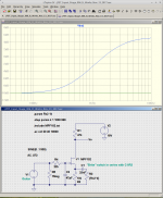
The attached screenshots show the schematic, and an FFT of the simulated output with a 500 Hz, 2 Vpp sine wave input.
The fundamental and several harmonics are very clear, but, interestingly, there are also sub-harmonics below 500 Hz, and non-harmonically related IMD products in between the 2nd, 3rd, 4th, harmonics.
KMG really captured a lot of triode-like complexity in his LND150 circuit...amazingly good work!
Simulations can be a terrible time-sink, but they can also, under the right circumstances, guide one to a good solution that reduces time taken to actually build something that works. That happened for me last week with the "de-nastifying filter", and I'm hoping it will happen again when I try to get a more "triodey" clean tone out of this thing.
There will be something real from the work-bench in my next post here, I promise!
-Gnobuddy
Attachments
And a real report from the work bench: I finally got everything hooked up, and played a solid-body electric guitar through the de-nastifying filter I built.
It worked very well. No more nasty harsh timbre, just the usual rather unattractive, sterile-sounding solid state guitar amp clean tone. Progress!
So, on the plus side, it looks as though I've managed to lick the problem of using non-guitar speakers for electric guitar, and still getting acceptable sound quality. This is a huge win for me, because it is relatively easy to find thrift-store boom box speakers up to about 6" - 7" diameter for just a few bucks. On my current budget, it has to be that cheap, or it's not going to happen at all.
On the minus side, that one lonely JFET at the input isn't contributing any noticeable goodness to the clean tone. Something has to be done to improve the clean tones.
I was more or less expecting that, so this is not much of a setback. And thanks to Printer2's link to KMG's work, I have an excellent lead to follow. I also have a few LND 150s in the parts box, but unfortunately, no Schottky diodes at all.
I'm now re-thinking some earlier decisions I made with this amp. Boom-box speakers have other major differences from real guitar speakers - they are much less efficient, and they are designed to work best in sealed or ported enclosures that are carefully matched to their Thiele-Small parameters.
The huge reduction in efficiency translates to a huge reduction in loudness, but for my purposes, this is actually a good thing. Neither I nor my friend will go deaf, and class D power amp modules are now so cheap that it's fairly easy to throw 40 or 50 watts at the speakers if you do want them a bit louder. (But they still won't get up to ear-damaging SPL levels, which is good.)
The other issue - working best in a properly matched enclosure - is the one that is giving me second thoughts. I pulled these two woofers out of two thin, extraordinarily ugly, MDF ported enclosures, and transferred them to a better-looking enclosure, because I want to give this amp to a friend, and I want it to look at least reasonably good.
But now I'm thinking I should have left the woofers in their factory-stock boxes, and found a way to make those look better, or just used one woofer. The thin MDF and single speaker would be lighter for my friend (he has a physical disability). And the ported and properly tuned enclosure might produce stronger bass - which my friend usually likes.
I'm going to stay focused on the electronics until I feel it's satisfactory, though. So the next step is to start working on getting better clean tones.
-Gnobuddy
Good to see this topic in its own thread, I am sure it can suck up as much time as the 100 buck thread. ")
Once I get over my ukulele building I should have some time to mess with fets. I have some LMD150's but it would be nice to simulate the same circuit at finger friendly voltages.
Once I get over my ukulele building I should have some time to mess with fets. I have some LMD150's but it would be nice to simulate the same circuit at finger friendly voltages.
There are seven and a half billion people on planet earth, and seven people browsing this sub-forum. This topic will be just as thoroughly ignored anywhere on this forum, whether in its own thread, or the hundred-buck amp thread.Good to see this topic in its own thread
I'm hoping for the same thing.I have some LMD150's but it would be nice to simulate the same circuit at finger friendly voltages.
I'm running my class D audio power amp module of a 24V DC wall-wart, so life will be much simpler if the entire preamp runs on something less than 24 volts.
All the preamp breadboarding and prototyping so far has been powered by two 9V flat batteries in series.
-Gnobuddy
There are seven and a half billion people on planet earth, and seven people browsing this sub-forum. This topic will be just as thoroughly ignored anywhere on this forum, whether in its own thread, or the hundred-buck amp thread.
Yeah but they are seven of the more underrated bunch of the seven and a half billion.
Did that come out right?
Yeah but they are seven of the more underrated bunch of the seven and a half billion.
Did that come out right?
Ego understood, over.
As someone who struggles to find Useful Stuff(tm) a few years down the track (try finding anything in the "Beyond the Ariel" thread) having it's one thread is a good idea.
Tubelab also noted that part of the "sound" of PP amps is powersupply IMD . Can't find that thread either
Tubelab also noted that part of the "sound" of PP amps is powersupply IMD . Can't find that thread either
I'm the type of person who can never find anything again if I file it carefully away. But if I throw everything in one big pile, then I know where to look for it.As someone who struggles to find Useful Stuff(tm) a few years down the track (try finding anything in the "Beyond the Ariel" thread) having it's one thread is a good idea.
I remember reading a write-up of an undergraduate engineering project, in which someone took a Bassman, added voltage regulation and filtering to the power supply, and then claimed the amp sounded utterly lifeless and awful.Tubelab also noted that part of the "sound" of PP amps is powersupply IMD . Can't find that thread either
That conclusion was 100% subjective, and so strongly worded that I found I could not take it very seriously.
Along the same lines, I once found an online discussion on guitar amps that "note switch", with audio clips demonstrating the phenomenon - the pitch of the note heard from the speakers jumps randomly between two different values, while the guitar is putting out one single note the whole time.
This was being described as a very good thing for an amp to do. But as a musician, I utterly hate the idea - I've spent many thousands of hours learning to play the "right" notes, and the last thing I want is an amp that arbitrarily emits something other than the note I've chosen to play!
I think the same is true for IMD. Rock guitarists who enjoy playing heavily distorted dyads ("power chords") might like the extra harmonic texture from those IMD products, which thicken up the two-note "power chord" sound. But people who are more prone to like the sound of complex, multi-note jazz chords will hate audible amounts of IMD, which ruin the sound of those complex chords. The typical blues or pop or country guitarist will be somewhere in between.
My point is that I think "good electric guitar sound" means very different things to different people, and I think that can make it quite hard to find common ground, or even to understand each other, sometimes.
Case in point, I've just spent a good part of a week coming up with a way to tame a harsh, penetrating guitar tone, trying get a smoother and more pleasant overall clean tone. But there are probably plenty of guitarists eager to "cut through the mix", who would be very happy to have that aggressive, penetrating tone I hated so much...
Back on topic, I spent a couple of hours today tinkering with KMG's LND150 triode emulator circuit in LTSpice, trying to make it work at 24V DC rather than 290 V DC.
I didn't really succeed in that attempt, but I learned a few things along the way, including the fact that the negative supply rail for the MOSFET sources is essential. Biasing the gate positive and adding a coupling cap does not work because of the asymmetrical "grid current" flowing through that coupling cap, which mucks up the bias point and waveforms.
And that is another key thing about the LND150 pseudo-triode circuit; the softly rounded negative half-cycles at the output come from softly diode-clipped positive half-cycles at the input, which in turn means the circuit is very sensitive to the source impedance feeding it. I'm not sure it would work at the input stage of an amp, fed directly from a guitar. I should look back at KMGs amp designs to see what he did with the input stage.
On a more promising note, at levels well below clipping, it seems easier to get somewhat pentode-like distortion from a simple FET gain stage with full source bypassing - meaning negative half-cycles at the output are longer and "sharper" than positive half-cycles. Exactly the opposite of what KMG gets out of his diode-clipped triode emulation stage.
Personally, I like the bright, chimey cleans from a small signal pentode, so I'm hoping I can persuade a JFET to sound a bit like one.
Finally, so there is something other than a wall of text in this post, here's something else I've been working on today: an active one-knob tone control circuit, essentially an active version of the "Big Muff" tone control.
I'm hoping that my work EQ'ing the amp for a good clean base tone will mean that heavy additional tone controls won't be necessary, and a simple tilt control will do the trick.
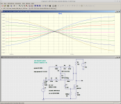
I started with this: One-Knob Wide-Range Tone Control
As you can see, I modified it (in LTSpice) to use a single MOSFET instead of an op-amp, scaled the components to give a much higher input impedance and less loading on the active device, tweaked it for more treble and bass control range, and moved the crossover frequency point down to around 500 Hz to suit guitars better than the original 1 kHz.
The attached frequency responses are plotted from only from 80 Hz to 5 kHz, the actual frequency range of interest to us guitarists.
The friend I'm building this amp for doesn't get along with complicated gizmos with too many knobs on them, which is another reason I want to keep the tone control to one knob if possible. I'm thinking a three-knob design, with gain, tone, and (master) volume knobs.
Active tone controls must be kept out of clipping, otherwise the frequency response and distortion goes to he11 in a hand-basket, so I'll have to be careful where this goes in the preamp audio chain. I will have around 20 volts of power supply voltage, so hopefully it will not be too hard to make sure this never clips.
It does weigh on my mind that I don't think I've ever heard anyone praise a tilt tone control in a guitar amp. But those amp designs were not already voiced for good clean tone before the tilt tone control was added, so I'm hoping the story will be different this time.
-Gnobuddy
Attachments
Tubelab also noted that part of the "sound" of PP amps is powersupply IMD . Can't find that thread either
I remember hearing a sound bit of someone playing a tube amp and they got it to growl in a neat sort of way. It sounded like something that I would hate in a HiFi amp, or even a clean guitar amp. I remember playing the clip (Youtube maybe) into my FFT analyzer and seeing obvious 50 or 60 Hz IMD when the amp growled. I can't find it right now either, but I'm guessing it's buried deep in the HBAC thread.....I somehow think it was a SE amp, like a Champ clone, but I could be way off.
This is a very old soft limiter circuit from the 1980's to emulate valve type distortion.
Its a bit more subtle than the usual fuzz box circuit.
For a guitar it needs quite a bit of front end gain to make the circuit work well.
Its a bit more subtle than the usual fuzz box circuit.
For a guitar it needs quite a bit of front end gain to make the circuit work well.
An externally hosted image should be here but it was not working when we last tested it.
Thanks for sharing.This is a very old soft limiter circuit from the 1980's
I wonder how that would sound if the BJTs were replaced with a complimentary pair of enhancement MOSFETs. Even softer distortion, or would the MOSFET body diodes ruin it?
-Gnobuddy
I remember playing the clip (Youtube maybe) into my FFT analyzer and seeing obvious 50 or 60 Hz IMD when the amp growled......I somehow think it was a SE amp, like a Champ clone, but I could be way off.
I've been thinking a bit about this (long bus trips to site) and postulate that there's something going on with screen voltage modulation: as the screen current increases it's effective impedance drops vs. what ever capacitance is holding it up, causing mains ripple on the screen and thus mains IMD at high volumes. I was visualising the I/O curve plot over the first few cycles of 1kHz pulse - should look rather pretty. I'm a long, long way from my workbench so this'll remain theory for a while.
Last edited:
Progress!
Today was a holiday here in BC, so I got a little time at the electronics workbench.
I decided to put together a simple JFET input stage to see if I could get it to warm up the cold and sterile clean tone from the amp I'm building.
Some earlier tinkering with LTSpice had suggested that biasing a JFET fairly close to cutoff would produce more harmonic distortion, compared to a more typical operating point. So I plugged an MPF102 into the breadboard, added a 1 megohm gate resistor, and a rather large 10 kilo ohm source resistor.
The JFET biased up with 1.5 volts DC across the 10k source resistor, i.e., quiescent source current was 150 micro amps.
With my 18 volt power supply, a 56k drain resistor would have been about optimum. The nearest 1/4 watt resistor I had was 47k, so I plugged that in. The DC operating point looked just fine (9.7 V at the drain, with 17.2V DC from the two 9V flat batteries in series).
With a 10k unbypassed source resistor, and a 47k drain resistor, voltage gain is quite small, something a bit less than 4.7 times (or 13 dB).
I added a 1/4" jack at the input, and AC coupled the output of this JFET to my "de-nastifying filter", which, in turn, went to the input of the class-D audio amp module. That module has its own volume control, acting as the master volume in the chain.
I plugged in the same beater Epiphone I mentioned earlier, and strummed a few chords. Two things were immediately noticeable:
1) The clean tone was sweeter. Certainly not as lush as a good valve amp, but no longer thin, cold, sterile, and slightly harsh. To my ears, it had crossed the line from "This amps clean tone is just tolerable" to "This amps clean tone sounds okay".
2) The amp sounded duller than before, as though the treble had been turned down.
The first outcome was great - exactly what I'd been hoping for. Yay!
The second one, though was unexpected. I had designed the "de-nastifying filter" to produce the best clean tone I could get (for my taste). Now I had added a flat-frequency-response JFET input pre-stage, and suddenly, my ears wanted more treble?
I went back and forth, inserting and removing the additional JFET pre stage, and came to the same conclusion each time.
My best guess is that the added harmonic distortion from the additional JFET, removed some of the apparent harshness I'd been hearing at high frequencies, and the reduced harshness led my ears to now want a bit more treble from the amp.
I could fairly easily go back and modify the speaker-emulation part of my "de-nastifying filter" to widen the bandwidth a little more. All it would take is scaling down the three 12 kilo ohm resistors in the low-pass filter section, maybe to 10k or 8.2k. That would get me a bit more treble.
But I decided to try a simpler solution first, a 33 nF "bright cap" to partially bypass the JFET's 10k source resistor starting above 500 Hz, with a 1k resistor in series with the cap to level off the treble boost at around 5 kHz (see LTSpice schematic).
It worked very well. Experimenting, I found I liked the amp both with and without the additional "bright cap", as it allowed a wider range of guitar tones. Now I have to decide if I want to actually add a "Bright" switch to the amps set of controls.
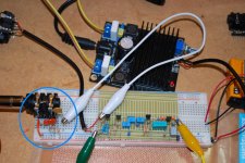
Here's a pic, and an LTSpice screenshot. The MPF102 itself is lost against the black body of the 1/4" input jack, but it's there.
Takeaways for me from today:
1) Get the clean tone right before voicing the amp! Sweetening the cleans might lead you to want more treble from the amp, because the treble no longer hurts your ears!
2) Biasing a JFET "colder" seems to enhance the type of guitar distortion that sounds good for clean tones. The MPF102 JFET biased to 1 mA at the input of the "de-nastifying filter" didn't sound audibly "valvey" at all, while an identical JFET biased to 0.15 mA sounds much more "valvey".
3) A good test to see if there's enough THD to sweeten the cleans is to play a dyad (two notes at one time) on the guitar with a fairly heavy picking hand, and listen for the slight roughness of intermodulation distortion.
I usually try major thirds, perfect fourths, and perfect fifths (the last one being the usual rock "power chord"). If there's a little "growl" in the dyad, easing up on the picking hand will usually produce a nice sweet clean tone.
I'm pretty happy with the way this has gone so far. I started with thrift-store speakers and power supply, and a cheap Ebay class D power amp module. It sounded utterly nasty at first, but I've managed to turn it into something good enough to be enjoyable to play through (clean tones only so far).
I won't be embarrassed to give this as a gift, now. To my ears, the clean tones are already better than the usual cheap solid-state Fenders, Marshalls, and so on, and the overall sound is much better than the Roland Microcube my friend is using now. That little toy has negligible audio output below 1 kHz or so.
There is no tone control yet, so I do have to work on that. I also have to decide whether I'm going to try to add one more JFET stage for more "valveyness", and/or also build a distortion circuit. Finally, I have to decide if I want to re-house the speakers yet again. While the amp sounds much better now, there is still some "boxiness" - I think the speaker enclosure I'm using now just has a bad set of internal dimensions, and nothing will really fix it.
-Gnobuddy
P.S. I'm stepping the 1k resistor in series with the 33nF bypass cap between 1k and 1 meg in LTSpice, to simulate the effect of switching the "bright cap" in or out. The flat frequency response is with the cap switched out, of course.
Today was a holiday here in BC, so I got a little time at the electronics workbench.
I decided to put together a simple JFET input stage to see if I could get it to warm up the cold and sterile clean tone from the amp I'm building.
Some earlier tinkering with LTSpice had suggested that biasing a JFET fairly close to cutoff would produce more harmonic distortion, compared to a more typical operating point. So I plugged an MPF102 into the breadboard, added a 1 megohm gate resistor, and a rather large 10 kilo ohm source resistor.
The JFET biased up with 1.5 volts DC across the 10k source resistor, i.e., quiescent source current was 150 micro amps.
With my 18 volt power supply, a 56k drain resistor would have been about optimum. The nearest 1/4 watt resistor I had was 47k, so I plugged that in. The DC operating point looked just fine (9.7 V at the drain, with 17.2V DC from the two 9V flat batteries in series).
With a 10k unbypassed source resistor, and a 47k drain resistor, voltage gain is quite small, something a bit less than 4.7 times (or 13 dB).
I added a 1/4" jack at the input, and AC coupled the output of this JFET to my "de-nastifying filter", which, in turn, went to the input of the class-D audio amp module. That module has its own volume control, acting as the master volume in the chain.
I plugged in the same beater Epiphone I mentioned earlier, and strummed a few chords. Two things were immediately noticeable:
1) The clean tone was sweeter. Certainly not as lush as a good valve amp, but no longer thin, cold, sterile, and slightly harsh. To my ears, it had crossed the line from "This amps clean tone is just tolerable" to "This amps clean tone sounds okay".
2) The amp sounded duller than before, as though the treble had been turned down.
The first outcome was great - exactly what I'd been hoping for. Yay!
The second one, though was unexpected. I had designed the "de-nastifying filter" to produce the best clean tone I could get (for my taste). Now I had added a flat-frequency-response JFET input pre-stage, and suddenly, my ears wanted more treble?
I went back and forth, inserting and removing the additional JFET pre stage, and came to the same conclusion each time.
My best guess is that the added harmonic distortion from the additional JFET, removed some of the apparent harshness I'd been hearing at high frequencies, and the reduced harshness led my ears to now want a bit more treble from the amp.
I could fairly easily go back and modify the speaker-emulation part of my "de-nastifying filter" to widen the bandwidth a little more. All it would take is scaling down the three 12 kilo ohm resistors in the low-pass filter section, maybe to 10k or 8.2k. That would get me a bit more treble.
But I decided to try a simpler solution first, a 33 nF "bright cap" to partially bypass the JFET's 10k source resistor starting above 500 Hz, with a 1k resistor in series with the cap to level off the treble boost at around 5 kHz (see LTSpice schematic).
It worked very well. Experimenting, I found I liked the amp both with and without the additional "bright cap", as it allowed a wider range of guitar tones. Now I have to decide if I want to actually add a "Bright" switch to the amps set of controls.
Here's a pic, and an LTSpice screenshot. The MPF102 itself is lost against the black body of the 1/4" input jack, but it's there.
Takeaways for me from today:
1) Get the clean tone right before voicing the amp! Sweetening the cleans might lead you to want more treble from the amp, because the treble no longer hurts your ears!
2) Biasing a JFET "colder" seems to enhance the type of guitar distortion that sounds good for clean tones. The MPF102 JFET biased to 1 mA at the input of the "de-nastifying filter" didn't sound audibly "valvey" at all, while an identical JFET biased to 0.15 mA sounds much more "valvey".
3) A good test to see if there's enough THD to sweeten the cleans is to play a dyad (two notes at one time) on the guitar with a fairly heavy picking hand, and listen for the slight roughness of intermodulation distortion.
I usually try major thirds, perfect fourths, and perfect fifths (the last one being the usual rock "power chord"). If there's a little "growl" in the dyad, easing up on the picking hand will usually produce a nice sweet clean tone.
I'm pretty happy with the way this has gone so far. I started with thrift-store speakers and power supply, and a cheap Ebay class D power amp module. It sounded utterly nasty at first, but I've managed to turn it into something good enough to be enjoyable to play through (clean tones only so far).
I won't be embarrassed to give this as a gift, now. To my ears, the clean tones are already better than the usual cheap solid-state Fenders, Marshalls, and so on, and the overall sound is much better than the Roland Microcube my friend is using now. That little toy has negligible audio output below 1 kHz or so.
There is no tone control yet, so I do have to work on that. I also have to decide whether I'm going to try to add one more JFET stage for more "valveyness", and/or also build a distortion circuit. Finally, I have to decide if I want to re-house the speakers yet again. While the amp sounds much better now, there is still some "boxiness" - I think the speaker enclosure I'm using now just has a bad set of internal dimensions, and nothing will really fix it.
-Gnobuddy
P.S. I'm stepping the 1k resistor in series with the 33nF bypass cap between 1k and 1 meg in LTSpice, to simulate the effect of switching the "bright cap" in or out. The flat frequency response is with the cap switched out, of course.
Attachments
Last edited:
Thanks, Voltwide!
I don't have a clue what the ultimate guitar sound might be. I only know what I like, and I can make a reasonable guess what my friend (whom the amp is for) might like.
I'm pretty sure he would like built-in reverb, too, but that is beyond my time and budget constraints for this particular build.
I hope to make some progress on the tone control this weekend, and I'll try and get some oscilloscope waveforms to find out what that input JFET is actually doing to make such a nice improvement to the sound.
-Gnobuddy
I haven't made any significant progress with this project in the last few days, due to a combination of illness and work pressures.
I did do a quick experiment with just the guitar, input JFET stage, (schematic in post #33), class-D power amp, and speaker system. In other words, I removed the previously designed bass boost, 800 Hz notch, and steep treble roll off above 2 kHz, to try to hear the effect of the input JFET stage alone.
What did I hear? While the single JFET definitely sweetens up the timbre of the clean tones, it is not enough by itself to make this amp sound good. The 800 Hz notch and bass boost is still needed.
However, the aggressive treble roll off above 2 kHz doesn't seem to be needed to anything like the same degree as before. I may widen this up to 4 - 5 kHz for the next experiment.
With that roll off removed, the "bright switch" is too bright. I may try cutting the 33nF JFET source bypass "bright" capacitor to roughly half its value, i.e. 15 nF (or 0.015 uF if you prefer), moving treble boost above 1 kHz rather than from 500 Hz on up.
But I think I'm coming around to the one decision I did not want to make - I'm not going to be happy with this thing until I re-house the pair of speakers in a bigger enclosure. The big driver behind this decision is hearing once again how little bass these speakers produce in their current enclosure.
I think I will bite the bullet and build a box for them, with twice the internal volume of the original ported boombox enclosures (because both woofers are going in the same box). I saved both the original plastic bass-reflex port tubes, so I can re-use them as well.
I expect the new box, once built, will improve the bass response, and that in turn may mean that less bass boost EQ is needed.
-Gnobuddy
Great work Gnobuddy.
I have a question concerning the cold biased jfet stage:
When you added the cold bias stage in front of the de-nastifier,
wouldn't the added gain push the first stage of the de-nastifier a little harder?
Woudn't most of the added THD be coming from the first stage of the de-nastifier?
An unbypassed jfet stage, even at a "cold" bias point is still pretty clean.
There's not a lot of THD going on, because of the negative feedback of the source resistor.
Just for giggles, I simmed the circuit in post #33 at 100mv input at 500hz. No bypass.
I got a gain of about 4 and 0.06% THD.
Now I always take simulated THD figures with a grain of salt, but even if that figure is overly optimistic, that's not a significant amount of THD.
For whatever reason, unbypassed gain stages whether bjt, jfet or 12AX7 seem to sound "duller", like you said "as if the treble was turned down".
Depending on the output of your humbuckers, with the added gain stage, you could actually be pushing the 1st stage of the de-nastifier into some mild clipping.
Anyway, it seems like you are going to need at least 2 gain stages and maybe 3. Even a "clean" tube amp like a twin reverb has several percent THD.
I wish you the best with your speaker situation. I've never tried to use boombox speakers for guitar.
That thought crossed my mind a while ago as well, and may very well be the case. Here is the sequence of events as they transpired:When you added the cold bias stage in front of the de-nastifier,
wouldn't the added gain push the first stage of the de-nastifier a little harder?
Woudn't most of the added THD be coming from the first stage of the de-nastifier?
1) When I first added the JFET pre ahead of the "de-nastifier", the treble started to sound warmer and less harsh. There was also a wee little bit of "growl" if I strummed or picked the guitar fairly hard.
2) I replaced the guitar with an audio signal generator, and looked at the output of the "de-nastifier" on my 'scope. I saw some soft-clipping on one half-cycle (I think negative) coinciding with the bit of "growl" I'd heard earlier.
Because there is both a notch filter, and a low-pass filter in the chain, and everything in the "de-nastifier" is direct-coupled, it was a bit hard to tell where the clipping was coming from. But, like you, I assumed it was from the second JFET in the chain. The waveforms I was seeing had already been filtered through both the notch and the low-pass, so probably didn't look much like they did at the stage that caused them.
3) Since the "de-nastifier" was now sounding a bit lacking in treble with the JFET pre ahead of it, I tried running just the single input JFET stage into the class-D audio module.
This is where things get a little strange, because it sounded to me as though this single JFET was still producing better (less harsh-sounding) treble than the class-D module by itself. Switching in the "bright cap" produced too much treble in this case, somewhat predictably, with the heavy low-pass filtering in the "de-nastifier" removed.
I could not see any obvious nonlinear distortion on the 'scope (I was expecting to see negative half-cycles a bit taller than positive ones, like a pentode). So nonlinear distortion was certainly quite low, as your simulated results suggest.
And yet I seemed to be hearing a difference, a softening of the harshness. There seem to be two plausible explanations: one, I was delusional, and was hearing things I wanted to hear (a very common problem!) Two, the cold-biased JFET was doing something audible, perhaps softening the large initial transient voltage that goes with each pick attack on a string?
I should try full-bypassing that 10k source resistor to see what the open-loop gain is at such a low source current. Maybe open loop gain is pretty small, and there isn't all that much negative feedback, as a result?There's not a lot of THD going on, because of the negative feedback of the source resistor.
Incidentally, if you looked at the "triode emulator" paper by Dimitri Danyuk (Triode Emulator by Dimitri Danyuk | Field Effect Transistor | Amplifier ), there is apparently an optimum value of un-bypassed source resistance that modifies the nearly perfect square-law of the JFET into something close to the three-halves vacuum triode law. IIRC the optimum value is Rs = 0.84 Vp/Idss.
So my initial plan with that JFET pre-stage was to bypass the 10k source resistor with a cap in series with this optimum value "triode emulation" resistor. I never did, because it seemed to be doing something to improve the sound, even without it.
Thanks for doing that, always nice to have thoughtful input from someone else!Just for giggles, I simmed the circuit in post #33 at 100mv input at 500hz. No bypass.
I got a gain of about 4 and 0.06% THD.
Now I always take simulated THD figures with a grain of salt, but even if that figure is overly optimistic, that's not a significant amount of THD.
I should have attached my LTSpice .asc file, sorry about that, would have saved you a few minutes.
Gain of four is about what I expected (47k Rd, 10k Rs, so a gain of 4.7 if you had infinite transconductance). But THD of 0.06% is inaudibly low in my world, so a head-scratcher there.
There will be more developments with this project. The day before yesterday I had an idea for another new circuit idea to test, one which I am hoping will coax more low-order distortion out of a JFET. We'll see if it flies, or is a dud, like so many ideas turn out to be.
As you suggest, I have a fistful of MPF 102's in the junk box, so if all other attempts fail, I might go to multiple JFET stages with fixed attenuators in between, to try and build up more audible low-order harmonic distortion.
I'm finding the 24V DC power supply rail a bit limiting, there isn't much margin between no audible distortion, and the beginnings of outright clipping.Anyway, it seems like you are going to need at least 2 gain stages and maybe 3. Even a "clean" tube amp like a twin reverb has several percent THD.
The class-D power amp module is also fairly sensitive, so doesn't need a lot of gain ahead of it. If I go to multiple stages, I will have to throw away some gain with inter-stage attenuators.
I've never played through a 'Twin, but I ended up with an estimated 20% - 35% distortion in my little 2-W amp in order to get good "clean" tone! Most of that was from a single small-signal beam tetrode stage, built around a 6AG5.
I think it takes more THD to produce a good clean tone at low volume, compared to the monstrous power of a 'Twin. Probably because our ears don't hear treble well at low loudness levels (Fletcher-Munson contours).
Necessity is the mother of invention in this case.I wish you the best with your speaker situation. I've never tried to use boombox speakers for guitar.
Clearly I'm not going to get "cone cry" which Hi-Fi people hate, but guitarists love. But the intended recipient of this amp now plays clean through a Micro Cube, which produces a thin, cold, bassless, miserable excuse for guitar sound.
(The Micro Cube does a passable "rawk" guitar sound, but my friend always plays clean.)
So my primary goal is to end up with something that has better clean tone than that toy of a Micro Cube - and I think that is definitely achievable, and in fact, has already been achieved.
Oh yeah, there is the Yamaha THR series of amps to think about - little toys that used powder-puff sized speakers, and managed to get quite a following from lonely closet guitarists who only ever play inside their apartments.
But Yamaha, from their long history with electronic keyboards, knows a lot about squeezing acceptable bass out of tiny speakers and cabinets.I bought some wood yesterday, and will try to put together a better cab starting this weekend. After that, back to the electronics (unless I tire of sawdust first, and can't resist the urge to try out that new idea I mentioned!)
-Gnobuddy
Bingo! Now that's the kind of talk I like to hear. Why is it that nobody ever takes that transient into consideration? With humbuckers, the transient can be huge, over 2V peak. 20db over the nominal signal, a nasty spray of harmonics, clearly visible on a scope and present every time the pick hits the strings! It's got to have an effect on the overall sound.... the cold-biased JFET was doing something audible, perhaps softening the large initial transient voltage that goes with each pick attack on a string?
I have a theory: one reason a lot of solid state amps sound like crap is that they don't deal with the transient very well.
An opamp based solid state amp will either pass the transient verbatim, or it will hard clip to the supply rails. Sure there's usually some tube screamer and/or Rat style diode clipping going on, that can sound relatively ok for "rawk" but not so well for cleanish sounds.
The twin reverb gradually "tames" the attack transient as it travels through the signal path, through a combination of 5-10% THD in each gain stage, cumulative miller capacitance, soft clipping in the phase inverter, hard clipping in the power tubes, poor transient response of output transformer due to inductance.
The result is a "crisp" sound, not "harsh" with a certain "sheen", that I call "gling"
I use the twin as a reference because I have one and just about anything you plug into it sounds majestic. Clean that is. To get it to break up, it is excruciatingly loud.
I'm finding the 24V DC power supply rail a bit limiting, there isn't much margin between no audible distortion, and the beginnings of outright clipping.
This is another problem that is rarely mentioned. Most people seem to just go ahead and build 9v high gain buzzboxes.
A couple of approaches.
1. The KMG approach. High voltage.
2. The runoffgroove approach. Use several low gain Fetzer Valve gain stages, with attenuation and very mild diode clipping between stages.
QUOTE] there is apparently an optimum value of un-bypassed source resistance that modifies the nearly perfect square-law of the JFET into something close to the three-halves vacuum triode law. IIRC the optimum value is Rs = 0.84 Vp/Idss.
[/QUOTE]
A quick trip to LTspice. I already had a Fetzer valve circuit simmed, this one with a 2n5457
Vgsoff = -1.59v Idss = 3.35ma. Using the resistor values computed at runoffgroove website, at 24v.
Gain about 7
Input 100m - 0.52% THD
Input 500m - 2.7% THD
Input 1V - 5.9 % THD
Input 1.5V - 10.7% THD
input 2V - 16.25% THD onset of clipping
This looks pretty good. Actually fairly close to a 12AX7 regarding input level vs THD.
The Fetzer stage does not attempt to model a tube's grid current in overdrive conditions, but the runoffgroove guys use Rat style diode clipping with 100k series resistor, this is very mild, very rounded off clipping, nothing like an actual Rat.
There will be more developments with this project. The day before yesterday I had an idea for another new circuit idea to test, one which I am hoping will coax more low-order distortion out of a JFET. We'll see if it flies, or is a dud, like so many ideas turn out to be.
Looking forward to it.
I bought some wood yesterday, and will try to put together a better cab starting this weekend. After that, back to the electronics (unless I tire of sawdust first, and can't resist the urge to try out that new idea I mentioned!)
Good luck with the cab. It's got to be difficult when you don't know the Thiele-Small parameters and you are trying to make a ported cab. Unless you have a way to measure that stuff. I've never tried to build a ported cab, only sealed and open back.
-MD
Right? And the usual Fender input-stage 12AX7 is biased to only around Vgk~ -1.5 volts, and we know grid current starts to flow at maybe -0.9 volts. So it would seem that any positive signal peak greater than 0.6V or so from the guitar will start to be clipped/rounded/softened by input-stage grid current flow, in combination with the high source impedance of a guitar.Why is it that nobody ever takes that transient into consideration? With humbuckers, the transient can be huge, over 2V peak.
Once I realized this, I stopped using voltage dividers to bias the grid of JFET buffer stages the "proper" way, so they would have maximum input headroom, Hi-Fi style. Now I just tie the gate to ground with a 1M resistor, and with the batch of MPF102 JFETs I've been using, the source always ends up at between +1.5 and +2.0 volts.
That's not too different from the usual 12AX7 stage with 1.5k cathode resistor and 100k anode resistor. And, so far, I've never heard any signs of bad clipping from these JFET stages - instead, there seems to either be no audible effect at all, or, if cold-biased, some reduction in harshness.
I agree on both counts - I have thought the same thing for some time now. No proof yet, I haven't collected waveforms or anything, but my ears suspect the same thing as yours.I have a theory: one reason a lot of solid state amps sound like crap is that they don't deal with the transient very well.
<snip>
The twin reverb gradually "tames" the attack transient as it travels through the signal path
No "gling" from my JFET attempts so far, unfortunately.The result is a "crisp" sound, not "harsh" with a certain "sheen", that I call "gling"
But less harshness than op-amp input stages, for sure.This is something I want to try at some later point. I am very impressed by the sound clips KMG posted. Assuming they're legit, and KMG wasn't playing a practical joke on the world, his work seems to be far ahead of anything else I've heard from a solid-state guitar amp, analogue or digital. He even got "gling" out of a handful of LND 150 MOSFETs!1. The KMG approach. High voltage.
KMG's work prodded me to get some more LND150s and a few small-signal Schottky diodes (they seem to be getting harder to find in through-hole packaging). Now I just need the time and energy to explore some of his work.
That's very good information, thanks for sharing!This looks pretty good. Actually fairly close to a 12AX7 regarding input level vs THD.
I'm going to cheat like crazy. I cut open one of the original thin MDF boombox speaker cabs (because I couldn't figure out any other way to get the driver out, it's a long story). But, learning from the first one, I kept the second box intact, and have measured all internal dimensions, so I know the internal volume of the original factory-designed ported box. I also saved both the original moulded-plastic port tubes.Good luck with the cab. It's got to be difficult when you don't know the Thiele-Small parameters and you are trying to make a ported cab. Unless you have a way to measure that stuff.
So all I have to do is build a new box with twice the internal volume of the original, and mount both woofers and both port tubes in it...and I should end up with the original box / port tuning. Close enough for guitar, I'm hoping.
These boombox woofers are weird in another way - DC resistance of the voice coils is around 11 (eleven!) ohms. I'm guessing nominal speaker impedance is supposed to be around 15 - 16 ohms. Not something I expected to find in a boom-box, and not ideal for use with my (stereo) class D power amp module, which is designed to drive its rated maximum power into 4 ohms or so.
Still, I figure both woofers together will put out around 35 watts, max, with these BTL chips powered from a regulated 24V DC supply. That should be more than enough for the intended usage.
I think there is a good reason why nobody builds ported cabs to use with typical tube guitar amplifiers. This belief was triggered by the entirely coincidental fact that, not long ago, someone on the Music Electronics Forum asked about the output impedance of a typical valve (tube) guitar amp.I've never tried to build a ported cab, only sealed and open back.
After some head-scratching, I realized we could make a good guesstimate, starting with the fact that the 6V6 datasheet says a 6V6 has around 80 kilo ohms anode resistance.
Let's say we have the usual 8k Raa output transformer, stepping down to an 8 ohm speaker. Each 6V6 sees one half of the OPT, or a primary impedance of 2k. So the impedance ratio seen by one 6V6 is 2000 ohms / 8 ohms, or 250 times.
If the OPT steps down the primary impedance 250 times, then that 80k anode resistance of the 6V6 should look like (80000/250) ohms from the speaker side of the OPT. That is a whopping 320 ohms source impedance!
With class AB operation, both 6V6s will be in action much of the time, so it's probably reasonable to assume the amp's output resistance will be halved - 160 ohms or so.
Leo usually used a few decibels of negative feedback in his amps, which will lower that 160 ohm number a bit more. Say he had 10 dB of global negative feedback - around 3.2 times - then the amp's output resistance would be lowered to around 50 ohms.
This was shockingly large to me - I grew up with solid-state power amps which have output impedances that are fractions of an ohm, and loudspeaker drivers designed to take advantage of that low source impedance to flatten their bass response.
But when you put 50 ohms of source resistance in series with an 8 ohm loudspeaker, all the Thiele-Small stuff goes out the window - there is virtually no electromagnetic damping, so the speaker will have a huge hump in its bass response. Driver Q will be up around Qms, typically between 3 and 10, rather than down around Qts, typically between 0.2 and 1.0.
With the Q of the speakers fundamental bass resonance completely out of whack, there is no way you can tune a cab to it. The speaker is already horribly under-damped.
Maybe that's why open-back cabs - which have very poor deep bass response, and acoustically cancel out the big bass hump - have been so popular in valve guitar amps for seventy-odd years?
For my current project, though, I'm using a solid-state class D amp module, so I'm assuming output impedance will be well under an ohm, and the original boom-box ported enclosure will work reasonably well. I guess I'll find out in a few more days!
-Gnobuddy
- Status
- This old topic is closed. If you want to reopen this topic, contact a moderator using the "Report Post" button.
- Home
- Live Sound
- Instruments and Amps
- Tube Emulation & EQ