I've just finished modding mine:
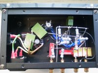
1. replaced 0.33uF input caps with pairs of 0.22uF Wima FKP (0.44uF total)
2. replaced 1uF output caps with 2.2uF Wima MKS
3. bypassed rectifier with 0.1uF Russian K71-7 polystyrol
4. bypassed B+ feed with 0.1uF Russian K71-7 polystyrol
5. bypassed AC heater feed with 0.1uF Russian K71-7 polystyrol
6. replaced stock valves with Russian 6J1P-EV
I think the stock output caps are a real limitation - these were the last thing I changed and brought about the biggest improvement. Ideally I'd have used something better than MKS but there was no way I was getting an obbligato or Epcos MKV to fit!
This buffer is now excellent between a TDA1543 nos-dac (passive I/V) and both a 41Hz amp6 and gainclone (both with passive pre). Clearly the passive output stage of the dac is not very happy driving a passive pre directly.
bigwill said:This circuit is intriguing, what is the purpose of the resistor connecting the cathode circuit back to the grid? Some kind of positive feedback?
It's just the normal DC grid return. The 1K resistor is the cathode bias resistor, and the 30K, the tail load. Returning the grid resistor to the junction of those two resistors gives normal bias. That connection also provides "bootstrapping" that makes the effective resistance of the grid resistor much greater than its DC value.
Does the bootstrapping also negate the miller effect somewhat? [/B]
It's a cathode follower, so no Cmiller is involved. Since the grid and cathode are at nearly the same voltage, the Cgk effectively becomes much smaller than its nominal value. The reverse transfer capacitance that would normally contribute to Cmiller simply becomes a grid-to-ground input capacitance.
i just get my Yaqin n moded already
the stock china tube with KQDD/K CV4010 tube
and internal i already change the cap for transformer to Elna and i bypass the signal cap to Mundorf ZN .... and all the resistor change to Kiwame Carbon resistor
i got 1 question ... the transformer output is how many volt is DC or AC
thanks
the stock china tube with KQDD/K CV4010 tube
and internal i already change the cap for transformer to Elna and i bypass the signal cap to Mundorf ZN .... and all the resistor change to Kiwame Carbon resistor
i got 1 question ... the transformer output is how many volt is DC or AC
thanks
An externally hosted image should be here but it was not working when we last tested it.
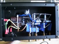
L700 said:i wanna ask what the black colour things that connect to 2 big cap thanks
Bridge rectifier, and it is quite clearly marked in the photos.
kevinkr said:
Bridge rectifier, and it is quite clearly marked in the photos.
thanks i no experience on electronics just started to understand
L700 said:
thanks i no experience on electronics just started to understand
the bridge rectifier is wut value n spec i really noob

Looks like one of those small 1A jobs, and PIV rating given the low voltages is probably around 400V. If I could see the part number stamped on the case that would help.
Many people have claimed to be able to hear massive differences when they swap a conventional rectifier or bridge for something using fast recovery diodes. I can't say definitively that I have, so I would not recommend spending large money here. Still these little bridge rectifiers have been the bane of my existence - they all fail eventually.
I'd recommend just replacing the bridge with 4 UF4007 diodes wired as a bridge. The banded end is the cathode end of the diode.
Since you are a newbie please wire up a 60W bulb in series with the ac mains (thus making a ballast lamp) and plug your Yaolin into that in case you make a wiring error - this will keep you from destroying the power transformer. Once you know it is right you can plug it in directly.
kevinkr said:Looks like one of those small 1A jobs, and PIV rating given the low voltages is probably around 400V. If I could see the part number stamped on the case that would help.
Many people have claimed to be able to hear massive differences when they swap a conventional rectifier or bridge for something using fast recovery diodes. I can't say definitively that I have, so I would not recommend spending large money here. Still these little bridge rectifiers have been the bane of my existence - they all fail eventually.
I'd recommend just replacing the bridge with 4 UF4007 diodes wired as a bridge. The banded end is the cathode end of the diode.
Since you are a newbie please wire up a 60W bulb in series with the ac mains (thus making a ballast lamp) and plug your Yaolin into that in case you make a wiring error - this will keep you from destroying the power transformer. Once you know it is right you can plug it in directly.
it writen RC207 on the case
bridge the 4 UF4007 its the diode got the marked is the end .... ?
its bridge like the picture below
thanks
An externally hosted image should be here but it was not working when we last tested it.
I swapped out the 100uF psu cap (the second one - after the series R) with a 680uF BHC Aerovox.
A layer of thickness in the lower mids / upper bass has disappeared, but bass now goes deeper and tighter. The mids and highs seem both clearer and smoother too.
This buffer is the perfect play-thing for the restless tweaker: it costs next to nothing, most of us will have tons of usable parts lying around and the results are great.
I'm currently using it after my Dac-AH (with passive output mod) so the buffer can be viewed as the output stage of my dac. It's much better than running the dac straight into a 10K pot before my gainclone.
Hi sharpi31, i am newbie can you kindly explain which point to connect the bypass cap?
quoting yours:
"3. bypassed rectifier with 0.1uF Russian K71-7 polystyrol
4. bypassed B+ feed with 0.1uF Russian K71-7 polystyrol
5. bypassed AC heater feed with 0.1uF Russian K71-7 polystyrol"
for:
"1. replaced 0.33uF input caps with pairs of 0.22uF Wima FKP (0.44uF total)
2. replaced 1uF output caps with 2.2uF Wima MKS "
i was inform that its 2x suppression cap. do you use suppression cap or just normal cap?
would you kindly explain more bout: "replacing 100uF psu cap (the second one - after the series R) with a 680uF BHC Aerovox"?
for resistor 30k ohm, can we substitute with 34k ohm resistor? as i have alen bradly avail in 30k ohm but its reading is 34k ohm. how bout the 300k ohm substitute with 240k ohm? thanks in advance
- Status
- This old topic is closed. If you want to reopen this topic, contact a moderator using the "Report Post" button.
- Home
- Amplifiers
- Tubes / Valves
- Tube Buffer 6J1 / 5654 (6AK5)