I've built three versions of the Aikido and didn't see any particular issues with matching. Perhaps I could have gotten 3dB better distortion figures if I bought ten tubes for every two that I used, but the distortion was sufficiently low that I didn't bother.
The 1M resistor won't hurt anything. I used 100k there, but I seriously think it makes about no difference.
The 1M resistor won't hurt anything. I used 100k there, but I seriously think it makes about no difference.
aikido coupling capacitor
Polar Bear,
How critical is that coupling cap? w.r.t sonic signature is it worthwhile to pay attention to it.
One of our forum friends already did experiment with audio caps:
http://www.ecp.cc/cap-notes.html
does it really matter anyway?
i've seen grounded grid aikido with transformer coupling, did u try this variant..
Cheers
Attachments
That polar bear has a name. Binky. You can look it up in Wikipedia.
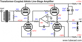
IMO, it's better to size that cap properly than get too obsessed with dielectric. If you make the input impedance 1M, then a high quality teflon or polypropylene film/foil cap will be practical and take you well beyond diminishing returns. Avoid so-called "audiophile" caps like the plague; quite a few that I've tried were "designed" rather than "engineered": not wrapped tightly enough, poor termination, inconsistent packaging, overly large size, unconscionable prices. A Wima FKP or one of the Russian teflons will be relatively inexpensive in the size you need (4n7-100n) and work essentially perfectly.
IMO, it's better to size that cap properly than get too obsessed with dielectric. If you make the input impedance 1M, then a high quality teflon or polypropylene film/foil cap will be practical and take you well beyond diminishing returns. Avoid so-called "audiophile" caps like the plague; quite a few that I've tried were "designed" rather than "engineered": not wrapped tightly enough, poor termination, inconsistent packaging, overly large size, unconscionable prices. A Wima FKP or one of the Russian teflons will be relatively inexpensive in the size you need (4n7-100n) and work essentially perfectly.
For all the audiophile angst, caps are much closer to perfect than are transformers- BUT... an input transformer carries some very nice benefits (noise rejection, bandwidth-limiting, ease of polarity inversion, ease of SE->balanced conversion).
Cap sizing is easy. Set the input impedance (let's say 1M in the case of a tube stage or a FET input). Choose the cap to give an f3 at least a decade below the lowest frequency of interest; 2 Hz is pretty common. Then use 1/(2piFR) To calculate the minimum required capacitance. For the 1M input and a 2Hz f3, C = 1/(6.28x2x1M) = 0.079uF. A 0u1 will be more than adequate.
Cap sizing is easy. Set the input impedance (let's say 1M in the case of a tube stage or a FET input). Choose the cap to give an f3 at least a decade below the lowest frequency of interest; 2 Hz is pretty common. Then use 1/(2piFR) To calculate the minimum required capacitance. For the 1M input and a 2Hz f3, C = 1/(6.28x2x1M) = 0.079uF. A 0u1 will be more than adequate.
Stuart,
Very nice..I'm slowly getting there. Ordered some 6sn7 and ecc88 tubes for aikido front end today...found cheap on e-bay (10 for 16$). I already got Aikido stereo pcb from John Broskie..I must admit, I have never seen such a well made pcb..
Now need to settle on SS buffer and power supply. I'm a bit obsessed in Gary Pimm's refined Swenson HV regulator but still need to make up my mind. The excellent HV regs can be found here:
http://www.pacifier.com/~gpimm/regulators.htm
All design credits go to John Swenson + Gary Pimm.
I do believe not a handful HV Regulators come close to modified swenson reg. This one champions:
Low impedence
Low Noise floor
Less smoke (Gary says bullet proof )
)
Later...
Very nice..I'm slowly getting there. Ordered some 6sn7 and ecc88 tubes for aikido front end today...found cheap on e-bay (10 for 16$). I already got Aikido stereo pcb from John Broskie..I must admit, I have never seen such a well made pcb..
Now need to settle on SS buffer and power supply. I'm a bit obsessed in Gary Pimm's refined Swenson HV regulator but still need to make up my mind. The excellent HV regs can be found here:
http://www.pacifier.com/~gpimm/regulators.htm
All design credits go to John Swenson + Gary Pimm.
I do believe not a handful HV Regulators come close to modified swenson reg. This one champions:
Low impedence
Low Noise floor
Less smoke (Gary says bullet proof
)Later...
Attachments
some thoughts on SS other half
I'm trying to sort out ss buffer. Already installed Multi Sim programme on my pc. Drew a schematic but noticed some silly trouble. I wonder how on earth people can not provide spice models for most commonly used solid state devices but can programme such a complex tool .
I was gonna simulate Ernest Landi double emitter follower buffer but looks like I need to spend more time on simulation...For my living, I already use a handful of CFD simulation tool,and I'm aware of the misleading character of these tools. One variable wrong, the outcome is in astry. But surely experience can not be substituted...There you go, I will have to bear a little pain of trial and error....unless some kind soul rescue me from this trouble.
I might opt out for D2S ( uses MOSFET) out put concept investigated by Ian Heggulan. Forgive me if I mis-spelled his name. i believe he is from newzealand and like many audio dillemma his cross over error correction topology never commercially engineered. (I might be wrong!)
Later..
I'm trying to sort out ss buffer. Already installed Multi Sim programme on my pc. Drew a schematic but noticed some silly trouble. I wonder how on earth people can not provide spice models for most commonly used solid state devices but can programme such a complex tool
. I was gonna simulate Ernest Landi double emitter follower buffer but looks like I need to spend more time on simulation...For my living, I already use a handful of CFD simulation tool,and I'm aware of the misleading character of these tools. One variable wrong, the outcome is in astry. But surely experience can not be substituted...There you go, I will have to bear a little pain of trial and error....unless some kind soul rescue me from this trouble.
I might opt out for D2S ( uses MOSFET) out put concept investigated by Ian Heggulan. Forgive me if I mis-spelled his name. i believe he is from newzealand and like many audio dillemma his cross over error correction topology never commercially engineered. (I might be wrong!)
Later..
Don,
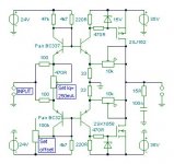
D2S buffer, original article (EE+WW) can be downloaded from:
http://pagesperso-orange.fr/francis.audio2/AmpHegglun.doc
I thought Aikido pre does provide very low output impedence.. with 6h30pi follower tube it could as low as 200R ?
http://www.tubecad.com/2006/06/blog0071.htm
Have you further refined triode fb amp?
Atiq
It does indeed have a low output impedance, but when you load it heavily, the distortion rises. There's several ways of looking at why that happens; for me, the easiest way to visualize it is to think of it in feedback terms.
A follower has low distortion because of the inherent feedback. Let's say I take a tube and load the plate with 10k and get a gain of 100. Now, if I take the same tube and load it with 1k, the gain will decrease. Let's say the gain with a 1k plate load is now 10. It's easy to see that moving the load into the cathode circuit, reducing the gain to near unity, will give me 40dB of feedback in the first case, but only 20dB of feedback in the second. So there's going to be at least ten times higher distortion in the second case.
And the picture is even worse than that- with a 1k plate load, the load-line is more vertical and the starting distortion will be significantly higher. Higher initial distortion and lower feedback is not a desirable combination!
I have simulated the non switching class-b SS buffer but I haven't got any written permission from the Inventor (Ernest Landi) for DIY use.
Results in simulation looks very bright. very low distortion upto full power with stair-case Fourier.
what is the forum rule on this matter? is it okay to post such an IP for DIY purposes?
Results in simulation looks very bright. very low distortion upto full power with stair-case Fourier.
what is the forum rule on this matter? is it okay to post such an IP for DIY purposes?
I just looked over at Wikipedia about patent rights and I was surprised as to the extent of protection, and for 20 years now. Says one cannot even build a model without permission. I always thought the protection was based on financial considerations from sales of products. However, it does not appear to exclude public discussion of patent ideas. After all, the patent itself is a public disclosure.
And practically speaking, it would seem the inventor would have to show financial impact from any DIY activity before filing any claims. How many people can there be making DIY non-switching class AB output stages who didn't buy some commercial product instead (that had the patent implimented internally)?
To be ultra safe, I would just state that the schematic is for philosophical discussion only. Then any DIYer that builds it are on their own as far as violations. I've certainly seen plenty of patented schemes posted without any special considerations mentioned. There is even an outrageous re- patent of the Darlington circuit recently. What else can you do?
Just my two cents. Maybe some moderator can give the official rules.
Don
PS: doing a forum search on non-switching or sliding bias will bring up a few other schemes for doing the same. I think Ian Hegglun also had another non-switching scheme, beside the buffer already mentioned. Probably was the "Fast power amplifier for audio" article in EW+WW. Mar 95, p240. Would be nice to find the article available somewhere to check it out. I have seen a schematic for his 50W class AB amp, and it has some clever differential sensors monitoring the output transistor currents. Appears to have a higher stage input impedance than the buffer.
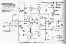
There is also an interesting scheme that uses crossed local feedbacks from the output emitter resistors back to CFP drivers. J. Broskie has mentioned it on his Tubecad site and simulated it. But he says it was mentioned to him by someone as a patented scheme. Unfortunately, no one seems to know what the patent # is.
And practically speaking, it would seem the inventor would have to show financial impact from any DIY activity before filing any claims. How many people can there be making DIY non-switching class AB output stages who didn't buy some commercial product instead (that had the patent implimented internally)?
To be ultra safe, I would just state that the schematic is for philosophical discussion only. Then any DIYer that builds it are on their own as far as violations. I've certainly seen plenty of patented schemes posted without any special considerations mentioned. There is even an outrageous re- patent of the Darlington circuit recently. What else can you do?
Just my two cents. Maybe some moderator can give the official rules.
Don
PS: doing a forum search on non-switching or sliding bias will bring up a few other schemes for doing the same. I think Ian Hegglun also had another non-switching scheme, beside the buffer already mentioned. Probably was the "Fast power amplifier for audio" article in EW+WW. Mar 95, p240. Would be nice to find the article available somewhere to check it out. I have seen a schematic for his 50W class AB amp, and it has some clever differential sensors monitoring the output transistor currents. Appears to have a higher stage input impedance than the buffer.
There is also an interesting scheme that uses crossed local feedbacks from the output emitter resistors back to CFP drivers. J. Broskie has mentioned it on his Tubecad site and simulated it. But he says it was mentioned to him by someone as a patented scheme. Unfortunately, no one seems to know what the patent # is.
atiq19 said:I have been wondering why compensation mechanisims are not frequently used in tube voltage amplification stages. Contrastly, I have seen the following methods being applied in solid state amps:
1. Miller compensation (known as Lag comp??)
2. Phase lead compensation ( used by JLH and others)
3. Combination of the above to tame over the top reactive load.
4. 2-pole compensation (well documented by D. Self)
5. PILL compensation scheme..
Now the question is why don't we see these in tube amps? Is it the case that tube amps don't suffer from instability issue?
Could someone shed light on this matter?
None of that is necessary when doing hollow state design. You're already starting out with a much more linear device, and even the absolute worst triode (i.e. 12AV7) is much better than any transistor in that regard. So, if you didn't absolutely ruin the open loop design, all you require is a small bit of error correction to compensate for the inevitable non-linearities (particularly xfmrs).
The only exceptions would be OTLs and some preamp designs. The main problem with OTLs is that running VTs into a nearly vertical loadline causes distortion. You'll probably need more gNFB to linearize the output stage in that case. Some preamps have enormous open loop gain, and will require some frequency comp due to the high levels of gNFB in these "glass op-amp" designs.
You don't want eeeeeeeeeeenormous amounts of gNFB anyway. One HS design I did I included variable gNFB (from 0 -- 13db(v)). Dial in the full amount of gNFB, and it really starts sounding "solid statey". Might be a good compromise value if you wanted to increase ease of use by eliminating that twiddle knob, but that much gNFB makes hard rock sound "subdued". About half the maximum gNFB sounds about right: enough to tame any residual pentode nastiness, but with enough "edge" to sound good.
but without gnfb, I am open to higher distortion (desirable SET sound by many listener) and uncontolled ouput impedence (???) or damping factor ...
Running open loop puts you at the mercy of your components. That's what NFB does: makes operation less dependent on the components. I always design for inclusion of gNFB. SET heresey, but you can always compromise and make it variable. That way, the "purist" can listen without it, and others can decide if and how much they'd like to add.
- Status
- This old topic is closed. If you want to reopen this topic, contact a moderator using the "Report Post" button.
- Home
- Amplifiers
- Tubes / Valves
- Tube Amp Compensation Q