Over time I've occasionally seen the position advanced that piezo tweeters can be pretty good, but you have to filter them the right way. I haven't heard a fancy pants piezo setup, so I've kinda wondered if it's true. A while back I saw some closeout piezos of the 2x5, 1016 type. They were super cheap, so I ordered 10. They lay dormant in my garage for a time, but now 2 of them will spring forth into a 6" 2-way to sing the song of their people. But can I get it to sound nice?
These will partner with a 6" buyout driver I got some long time ago. It's a buyout that says Taiwan 13014690W. DATS measurement and a modeling says 10L, sealed, f3 ~60 Hz.
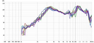
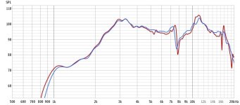
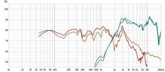
So the first thing I did was make up a test baffle and measure all the piezos on it. They start at about 3 kHz, and the biggest bummer I think is the variability 7-10 kHz where there is some sort of resonance. I chose 2 examples that are nominal / matched. All 10 and the selected 2 shown below.
These will partner with a 6" buyout driver I got some long time ago. It's a buyout that says Taiwan 13014690W. DATS measurement and a modeling says 10L, sealed, f3 ~60 Hz.
So the first thing I did was make up a test baffle and measure all the piezos on it. They start at about 3 kHz, and the biggest bummer I think is the variability 7-10 kHz where there is some sort of resonance. I chose 2 examples that are nominal / matched. All 10 and the selected 2 shown below.
Attachments
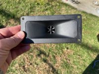
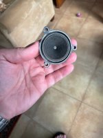
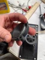
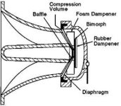
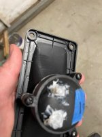
These piezos have 3 screws on the back. And I have 10 of em. So I figured I'd take one apart and have a look at it. It turns out they're super super simple! The piezo disk it glued to a conical diaphragm, the front and back shell clamp the edges of the diaphragm, the front of the shell is glued in to the horn. Hmmm, is there anything I can do to improve on this situation? I found a piezo diagram that listed a foam damper and a rubber damper in the back chamber, and as I looked around I didn't see anything like that on mine. So I got some speaker fluff to stuff in around the disk, on the front side. The back side I couldn't get to b/c the short leads wouldn't allow it to move around much. I could have unsoldered it, but I figured I'd start melting plastic all over the place if I tried that.
Attachments

Useful information here: https://www.diyaudio.com/community/threads/are-piezo-tweeters-frowned-upon.404381/#post-7481881
One of the challenges I had with these units is sealing them in the box. In retrospect, I think I'd suggest others not try to place these in a pressurized enclosure with a woofer, and maybe leave them out on top like some of the big old horn guys do.
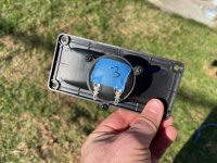
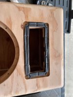
One issue was the rear of the flange is hollowed out and ribbed, so there is not a good flat surface to get a seal with. Especially b/c the screw ribs aren't as tall as the outside rib, so it's just destined to leak through the screw hole. I ended up putting some compressible weather stripping on the baffle under the flange to make the seal. After testing I removed the tweeter again, and saw the shape of the ribbing pressed into the weather seal, so I think that's doing its job.
I could still hear pumping noises around the tweeter, at the back of the horn (driving the woofer). So I have put some moretite rope caulk around the neck where the horn meets the compression chamber. Then I ended up caulking around the terminals as that didn't look well sealed. After that I seem to have a good seal around the tweeter. I did put a bit of butyl rubber and foil noise damping on the back of the horn also. The horn plastic seemed damped to start with, it didn't ring, but it isn't very robust so I thought I'd add some material to it.
Sealing the terminals and the neck may be beneficial to anyone following along, even if they don't enclose the tweeter with another driver.
Attachments
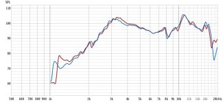
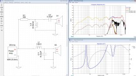
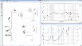
Which brings me to my in-box measurements, and crossover in XSim. R1 seems to do a good job of bending the two resonances on the tweeter down, but honestly I'm suprised that it looks as flat as it does here. The dip around 8 kHz looks to really fill in, I'm not sure if maybe some additional smoothing is sneaking in? I thought I had the woofer measurement windowed to leave only info above 200 or 300 Hz, but Xsim maybe guesses at LF content, or maybe the .frd had more info in it than I thought.
Attachments
Alright, can I get the xsim info in? If y'all want to have a play around with the XO design, let's see what we can come up with. I'm not really used to designing for piezos, so this was just a bit of playing around. I found a nice cheap closeout inductor, 20 AWG iron core for that 6.5 mH (at PE) so I already ordered that, but maybe there's a better way to do it.
Attachments
Hey I'd like to pop this back up, and ask for the input of local crossover gurus. I have a design posted above, but switching phases doesn't produce a null, it barely changes. So I'm not getting good addition at the XO. If I start dialing in z offset (I measured with a loopback timing reference, and think the existing offset is captured in the existing phase) to simulate a tweeter setback, I can see with an inch of additional delay I start getting good addition / null.
So I have messed with xsim some to try to get it to work and have so far been unsuccessful at improving things. Does anyone else think they can do a better job? Files are posted above, give it a go...
Alternatively, I have a 3D printer, so I could try to print an alt front horn that sets the piezo back a bit further. I don't know about horn design, so I'm not sure how I would do it without making FR trouble for myself. I don't want to scrap the boxes I have at this point (wood = $$$ !) so I want to use the existing baffle and tweeter cutout.
Whadya think?
I think the lack of null with inverted polarity is related to the asymmetry in the driver roll-offs and resulting acoustic filter order. I didn't try to fix that. I can't tell from your description if you're just messing with z offset in the model to try to produce a null in the graph or if that's actually producing a model that matches what happens when you reverse polarity of the actual driver.
I'm not a piezo expert either, so this is just a result of me screwing around. It's got more parts than your original design, but more flexibility also, and smaller inductor values. Power dissipation in R1 could get large depending on drive level. I didn't try to fix that either. By no means is this an optimized attempt, just a different approach than what you posted already.
Part of this was inspired by the posts talking about linearizing impedance with the resistor in parallel with the piezo.
Simpler than the previous one I posted, but less flexible from a tuning standpoint. Power dissipation in both resistors can get high. Load is more capacitive at higher frequencies.give it a go
Hey, thanks for taking a look, Mattstat! I kept avoiding putting a resistor in parallel with the Piezo, but it maybe it helps that notch work in a more predictable way. It's been a little bit, so I've already ordered a box of parts, they're resting in the garage. But I'll twiddle the values of your designs and see how they work. The impedance of that piezo makes everything seem to work a little funny.
I played in DSP with a setup once that wasn't making a good reverse-null on axis. Later I fixed that, and it managed to sound much more in-focus. I figure if you're not making a good lobe on axis, you are making a good lobe somewhere else... so ya I think it works best to do that.
Here's what I've come up with, this one makes a reasonable null, and only one more part. Maybe I'll get a chance to put it together this weekend...
a decent null when the tweeter polarity is flipped, if that's something you still want
I played in DSP with a setup once that wasn't making a good reverse-null on axis. Later I fixed that, and it managed to sound much more in-focus. I figure if you're not making a good lobe on axis, you are making a good lobe somewhere else... so ya I think it works best to do that.
Here's what I've come up with, this one makes a reasonable null, and only one more part. Maybe I'll get a chance to put it together this weekend...
Attachments
FYI, YMMV
https://web.archive.org/web/20180219170222/http://linear1.org/i/piezo.pdf
2006 Audiokarma
http://www.audiokarma.org/forums/index.php?threads/using-piezo-tweeters-wisely-a-how-to.79659/
Brian Steele - Blastoramas
http://www.diysubwoofers.org/projects/home/blastoramas/
Darren Kuzma - The Golden Boys - Parts Express
https://projectgallery.parts-express.com/speaker-projects/the-golden-boys/
Last edited:
So I built up the XO from my 2/24 post, and have been listening to it for about a week. I've had the speakers sitting on my coffee table in front of my listening position, so much closer than the normal stereo speaker position. As such they are far away from the walls, and throw a very nice and uniform sound stage! But maybe more to do with the speaker location than anything else. One thing I have noticed is that they are rather boomy. So I have made some XO confirmation measurements.
The measurements I showed earlier (2/24) were taken in my back yard, I thought I could just gate the measurement enough to see the XO region clearly. But for this question of boom, I took the system out to my driveway to do groundplane measurements. I measured the drivers raw, and then with the XO in place. The measurement with the XO matched the XSim prediction based on the driver measurements very well.

So the green trace in the FR window was the imported XO measurement result. But you can see the peak between 70 and 100 Hz. It sounded like a little too much. If we look at the raw driver vs the system FR, we can see that it's coming from the XO. My first thought was that it was DCR headed down to the woofer resonance, since it's a 4R woofer.

But I don't think that's it. I think it's my inductor combining with woofer impedance. There's a fair amount of inductance on this woofer, you can see system impedance headed up fairly steeply from 200 - 1000 Hz. So in order to get a XO up in the 2-3 kHz region where current is reduced, I end up with a L1 value that impacts that 500 Hz region in an unwelcome way. I tried putting in some impedance compensation, but it looks like I need the woofer inductance for the XO to resonate with to get the boost I wanted around 2.2 kHz. I played with this for a little while in XSim and didn't really get anywhere. So eventually I wondered if instead of bringing 500 up, if I could drag that bass boost down a bit. The largest bipolar electrolytic PE sells is 500 uf, and that with a bypass resistor allowed me to tame that bass hump a bit, sez XSim. So I've put the parts on order.
But that's all woofer stuff, this is really a thread about this Piezo. I do have a little bouncy-bouncy going on from 2k up to 10k, that these cleaner measurements show. So it looks like changing the balance of C2 and C3 can smooth that out. So this gives a prediction for XO version 4...

I'll build it, and we'll see how it does! In room the Piezo doesn't sound bad at all. It's not a fancy pants tweeter, but it's fine. The woofer boom and the HF lumps give a bit of a smiley-face contour, and with less boom I think a little less HF will match well. I'll wire it up when the parts get here and find out!
Hmm let me see if I can put the latest XSim in here for anyone who wishes to play along...
- A
The measurements I showed earlier (2/24) were taken in my back yard, I thought I could just gate the measurement enough to see the XO region clearly. But for this question of boom, I took the system out to my driveway to do groundplane measurements. I measured the drivers raw, and then with the XO in place. The measurement with the XO matched the XSim prediction based on the driver measurements very well.
So the green trace in the FR window was the imported XO measurement result. But you can see the peak between 70 and 100 Hz. It sounded like a little too much. If we look at the raw driver vs the system FR, we can see that it's coming from the XO. My first thought was that it was DCR headed down to the woofer resonance, since it's a 4R woofer.
But I don't think that's it. I think it's my inductor combining with woofer impedance. There's a fair amount of inductance on this woofer, you can see system impedance headed up fairly steeply from 200 - 1000 Hz. So in order to get a XO up in the 2-3 kHz region where current is reduced, I end up with a L1 value that impacts that 500 Hz region in an unwelcome way. I tried putting in some impedance compensation, but it looks like I need the woofer inductance for the XO to resonate with to get the boost I wanted around 2.2 kHz. I played with this for a little while in XSim and didn't really get anywhere. So eventually I wondered if instead of bringing 500 up, if I could drag that bass boost down a bit. The largest bipolar electrolytic PE sells is 500 uf, and that with a bypass resistor allowed me to tame that bass hump a bit, sez XSim. So I've put the parts on order.
But that's all woofer stuff, this is really a thread about this Piezo. I do have a little bouncy-bouncy going on from 2k up to 10k, that these cleaner measurements show. So it looks like changing the balance of C2 and C3 can smooth that out. So this gives a prediction for XO version 4...
I'll build it, and we'll see how it does! In room the Piezo doesn't sound bad at all. It's not a fancy pants tweeter, but it's fine. The woofer boom and the HF lumps give a bit of a smiley-face contour, and with less boom I think a little less HF will match well. I'll wire it up when the parts get here and find out!
Hmm let me see if I can put the latest XSim in here for anyone who wishes to play along...
- A
Attachments
- Home
- Loudspeakers
- Multi-Way
- Trying to get the best out of cheapo piezos