
Hi Carlos,
I am drawing a nice "final" schematic for you. I see you changed a few things on this livewire schematic.
- The .1R output resistor is now *before* the output cap.
- the output transistor capacitors changed from 7.5 to 10pF
- zobel filter on output was removed.
- 220pF cap on input was removed
- input resistor is adjustable
Are these changes important?
(I don't understand how this feedback works. Is there 2 global feedback returns?)
..Todd
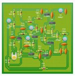
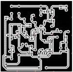
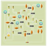
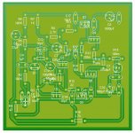
PCB my style .......
.... It's time to be here again with my PCB design size only 89mmX69 mm and I hoppe will be accepted by DX Corporation .") http://i39.tinypic.com/3497a7n.jpg and http://i41.tinypic.com/2nq002.jpg
http://i39.tinypic.com/3497a7n.jpg and http://i41.tinypic.com/2nq002.jpg
Regards Alex mm
.... It's time to be here again with my PCB design size only 89mmX69 mm and I hoppe will be accepted by DX Corporation .
http://i39.tinypic.com/3497a7n.jpg and http://i41.tinypic.com/2nq002.jpg Regards Alex mm
Soon i will take a good look at your work dear Alex
Now i have visitors in my house...latter i will see.
Thank you very much..boards are needed.
Now some comments..sorry...my word is misadjusted..so... doing strange letters and sizes.
..........................................................
Now let’s go to the comments... condensers, or capacitors are brand free.... also the dieletric material can be the ones they can find... just avoid electrolitic when possible...to los values use non electrolitic capacitors.
The output resistance, the 100 miliohms one (0.1 ohm) can be small.... ¼ or sligtly bigger... current will pass will be 1 ampere, and volts over that resistance will be 200 milivolts...so.... 200 miliwatts is the power there.... it may work alike a fuse if something goes wrong...it is there to damping purposes...to reduce the extreme strong basses and together the capacitors avoid High Frequencies (Radio Frequencies) oscilations because all transistors are high gain and high speed units
Also the power transistors emitter resistances will have less than 200 miliwatts passing..so.... can use a small one too.... so... R7 and R8 can be ¼ watt too.
Almost all capacitors to 35 volts, or 42 volts or 50 volts insulation voltage... exception to the bootstrap one that will need to be 63 volts... also the zobel capacitor must be 63V (C8)
R12 will be the stand by bias adjustment resistance...it is a good idea to split into two resistances.... a fixed of 680 ohms and a trimpot with 500 ohms... adjusting into 900 ohms means the trimpot will be pre adjusted to 220 ohms (almost half way...nice that?)...so... R12a... and R12b will be needed.
R2 will adjust the output half supply voltage....in our 36V case we need to adjust the output point..the output electrolitic condenser positive side to 18 V.... R2 will have half way as pré set...(nice?)
C5 is a critical condenser... CANNOT USE 220uf there...people may try to find 150uf or to associate 100uf plus 47uf in parallel...voltage there is 35V, or 42V or 63 Volts
Drivers and VAS DO NOT NEED HEATSINK....stand by bias is around 25mA and power output must have 200 square centimeters aluminium heatsink to each one of them...m a 12 by 16 centimeters aluminium plate, bent into “L” shape or “U” shape may fit..aluminiun thickness must be around 2 milimeters only.... two units...one to each output power transistor.
All transistors accept replacement...have to respect size, power and voltage only.... so... to VAS and drivers almost all T0220 transistors will fit....to output it is a good idea to use strong 2SC5200 and 2SA1943.....but even TIP41 and TIP42 will fit.
For a while, this is all i have to make comments about.
There’s no high watt resistance...if people wants... can use 1 watt into R17...no problems.
Carlos
Thank you very much Alex MM.... your board are aproved and
will be standard to the Dx Trust.
TAJ also produce Dx Corporation Standard Boards too..official boards too....he will make a rectangular board to fit his own needs, but maybe in the future he will make something squared to us.
So... we gonna have more options.
People can build the way they want...no problems.. the amplifier is safe and reliable... the way they build..if made not mistakes..then will work fine.
regards,
Carlos
Note to self (me not Doug): Never send Carlos preliminary schematics, because he posts them with problems and that causes endless confusion. I will put big "DRAFT ONLY - DO NOT POST" markings on it. Making them too big is a good idea, but it doesn't stop him.
The final one is not ready yet, but it will be uploaded here when the QC department has approved it.
..Todd
The final one is not ready yet, but it will be uploaded here when the QC department has approved it.
..Todd
- Status
- This old topic is closed. If you want to reopen this topic, contact a moderator using the "Report Post" button.
- Home
- Amplifiers
- Solid State
- Trust, the most delicious Dx Amplifier