Hi Christer!
The new and old terminology are not against wich other...the term current feedback is a way of being more especific about a amplifier.
The amplifiers are named as in the "old school" voltage ,current,tranconductance and transresistance.Nothing has changed.
To tell that a voltage amplifier is a current feedback voltage amplifier...is a adiction in the way the amp works and behave...is a more precise definition.
And this doesn't have nothing against what we have learned in the old books.
Tube_Dude said:The new and old terminology are not against wich other...the term current feedback is a way of being more especific about a amplifier.
Not at all. you must have misunderstood what the "old"
definition is. The "new" way of using current feedback means
something entirely different and is not a refinement of the
"old" defnition. The definitions ceratainly clash in the sense
that the same term is used for two different things. Just like
the prefix kilo being used both to denote 1000 and 1024, which
are clearly incompatible.
Can you tell me please...what is for you a current feedback amplifier???Christer said:
Not at all. you must have misunderstood what the "old"
definition is. The "new" way of using current feedback means
something entirely different and is not a refinement of the
"old" defnition. The definitions ceratainly clash in the sense
that the same term is used for two different things. Just like
the prefix kilo being used both to denote 1000 and 1024, which
are clearly incompatible.
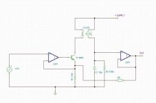
Attached is a block schematic of a simple CFB amp.
The input VCCS supplies a current (10mA/V in this case) to a current mirror.
The current mirror is loaded by a network that defines the OL performance (x1000 at dc, rolling off because of the capacitor). The voltage across this network is buffered to drive the output.
An external NFB network defines the CL performance.
This is what I think of as CFB these days.
Attachments
Tube_Dude said:
Can you tell me please...what is for you a current feedback amplifier???
Well, as I said, I have switched over to using the modern
terminology, so to me it means the same as to you, I think.
I hence assume you ask about the "old" definition. That has
nothing to do with with the inputs of the amplifier, they can
be high or low impedance, use voltage or current error, neither
of that matters. In "old" terminology, voltage feedback means
that you use the voltage over the load to create a feedback
signal (either voltage or current). Current feedback means that
you sense the current through the load (typically by inserting
a small resistor in the ground return from the load) and feed
back a proportional signal (voltage or current). See for instance
the link I posted before
http://www.ee.siue.edu/~alozows/cou...ce327/notes.pdf
This means that you can freely choose to use either voltage
or current feedback in the "old" sense together with either
a voltage or current feedback opamp in the "new" sense. The
two meanings are independent of each other.
Yes it is!!Ouroboros said:Attached is a block schematic of a simple CFB amp.
The input VCCS supplies a current (10mA/V in this case) to a current mirror.
The current mirror is loaded by a network that defines the OL performance (x1000 at dc, rolling off because of the capacitor). The voltage across this network is buffered to drive the output.
An external NFB network defines the CL performance.
This is what I think of as CFB these days.
")
Here we have a current feedback voltage amplifier.
But if you put a resistor say 1 Ohms for a 8 Ohms load in series with the load...and you take the feedback point from the resistor ...now we have a current feedback current amplifier!!
The schematic you post is very similar to the Pionneer Wide Range Linear Circuit in the essencial!
Tube_Dude said:Here we have a current feedback voltage amplifier.
But if you put a resistor say 1 Ohms for a 8 Ohms load in series with the load...and you take the feedback point from the resistor ...now we have a current feedback current amplifier!!
The schematic you post is very similar to the Pionneer Wide Range Linear Circuit in the essencial!
Oh, so you call those concepts voltage/current amplifier??
Even more confusing then, since now we have at least
four different names for those concepts, I think.
Bernhard said:Is everybody serious about that discussion ?
It is like the manufacturers use the term in their data sheets.
Low impedance inverting input.
Nothing else.
Ah, and because the commercial interests say it is so it must
be right, whatever the textbooks and universities teach us?
The fact is that this use of the term "current feedback" has
been overloaded upon an older and different use of it. Most
people probably use it in the newer sense and I have myself
reverted to that usage since I realized there was a newer and
seemingly more common use of the term and which also agrees
with the manufacturers. However, that does not mean that it
is the only right or possible meaning of the terms. Obviously
many people still use the term in the old sense and obviously
from this thread many didn't even know before that there is
a newer meaning of the term. It is very easy to believe that
what one has learnt oneself is the right thing. In reality
things often differ between textbooks, between universities
etc.
Mr.Peranders,
From OA-20, OA-030 from National, AB-091 from BB, SLOA021A, SLVA051 from Ti, it seem that
1. CFB has high bandwith and slew rate, lower distortion, suitable for high freq operation (>100khz)
2. VFB has good offset/DC operation, and noise, CMRR, PSRR, suitable for small signal and small voltage operation
These all are for Op-Amps
You have been in this so called CFB audio power amps for so long. What is your personal opinion of the sound it reproduces in Audio Range, compared to ordinary VFB amp?
I know that in a glance this CFB power amp produces more detail, faster bass reproduction. How far is the truth about an opinion of "Listening-Fatigue" in CFB power amp audio reproduction?
lumanauw said:How far is the truth about an opinion of "Listening-Fatigue" in CFB power amp audio reproduction?
I remember one posting that said: CFB never sounded right .
Yes, Bernhard,
I've done tests with CFB in Class AB and it's a washout, at least to my ears.
By the time you fixed the instability the music sounded tired, and washed out, particularly on the NPN output.
These comments do not necessarily apply to Class A, nor to SE. Of course, YMMV, but if you doubt this, you'd better build one and do some serious listening. PSpice does not reveal the sonics, sadly.
Cheers,
Hugh
Re: Who's censoring the internet???
Christer,
The notes at this link are what I consider the "classical" or maybe "old fashioned" definition of the various feedback types, including current series/parallel feedback. As you so clearly stated, this is incompatible with the new way of using CF for the case when the return node is low impedance. I am not claiming one or the other is the correct one, but just ask people to realise that there ARE two definitions so be ready to clarify what you mean.
Still, the old definition had the advantage of being precisely defined without a risk of confusion, see again the link, and also the easy check I posted earlier:
"if you short the output, and the feedback goes to 0, that's VF. If you disconnect the load, and the feedback goes to 0, that's CF. "
The new definition is more loose: low impedance node. What is low impedance node? Two connected emitter would be OK I guess? What if the two emitter currents are very low, impedance could go up to a k or so. What about amp_man's diagram with the 120 Ohms resistors? That still low impedance, or is it already drifting to VF? Again a lot of scope for discussions.
Jan Didden
Christer said:[snip] At least I found
evidence that there are still american universities who teach
their students the old terminology:
http://www.ee.siue.edu/~alozows/courses/ece327/notes.pdf[snip]Me, I know you are all wrong. I have known since childhood
that it is a häst.
Christer,
The notes at this link are what I consider the "classical" or maybe "old fashioned" definition of the various feedback types, including current series/parallel feedback. As you so clearly stated, this is incompatible with the new way of using CF for the case when the return node is low impedance. I am not claiming one or the other is the correct one, but just ask people to realise that there ARE two definitions so be ready to clarify what you mean.
Still, the old definition had the advantage of being precisely defined without a risk of confusion, see again the link, and also the easy check I posted earlier:
"if you short the output, and the feedback goes to 0, that's VF. If you disconnect the load, and the feedback goes to 0, that's CF. "
The new definition is more loose: low impedance node. What is low impedance node? Two connected emitter would be OK I guess? What if the two emitter currents are very low, impedance could go up to a k or so. What about amp_man's diagram with the 120 Ohms resistors? That still low impedance, or is it already drifting to VF? Again a lot of scope for discussions.
Jan Didden
Re: Re: Who's censoring the internet???
Yes, I agree it is the "classic" definitions. I didin't study the text
in detail, but it seems to comply fully with my old textbook. The
intersting thing is that this document is, as I undestand, lecture
notes from a course tought today, not many years ago or even
just a few years ago. That doesn't mean all other universities
teach it the same way, but it shows what I said before, not
even universities or textbooks agree. How does that classical
qute go "What is true in Heidelberg is a lie in Jena"?
Yes this is interesting. It is often just claimed for instance that
you can set the gain and bandwidth independently of each other
for a CFB amp and that it is Rf alone that sets the bandwidth.
As is stressed in the Intersil app. note, this claim assumes that
the output impedance is much lower than the value of Rg, which
is also clear from the equations.
CFB amps are very interesting, but also more difficult to analyze
than VFB ones, I think.
janneman said:
The notes at this link are what I consider the "classical" or maybe "old fashioned" definition of the various feedback types, including current series/parallel feedback. As you so clearly stated, this is incompatible with the new way of using CF for the case when the return node is low impedance. I am not claiming one or the other is the correct one, but just ask people to realise that there ARE two definitions so be ready to clarify what you mean.
Yes, I agree it is the "classic" definitions. I didin't study the text
in detail, but it seems to comply fully with my old textbook. The
intersting thing is that this document is, as I undestand, lecture
notes from a course tought today, not many years ago or even
just a few years ago. That doesn't mean all other universities
teach it the same way, but it shows what I said before, not
even universities or textbooks agree. How does that classical
qute go "What is true in Heidelberg is a lie in Jena"?
The new definition is more loose: low impedance node. What is low impedance node? Two connected emitter would be OK I guess? What if the two emitter currents are very low, impedance could go up to a k or so. What about amp_man's diagram with the 120 Ohms resistors? That still low impedance, or is it already drifting to VF? Again a lot of scope for discussions.
Yes this is interesting. It is often just claimed for instance that
you can set the gain and bandwidth independently of each other
for a CFB amp and that it is Rf alone that sets the bandwidth.
As is stressed in the Intersil app. note, this claim assumes that
the output impedance is much lower than the value of Rg, which
is also clear from the equations.
CFB amps are very interesting, but also more difficult to analyze
than VFB ones, I think.
Re: Re: Re: Who's censoring the internet???
Indeed. Part of the problem is that the "old" definition is, well, a definition. The new one started life as a marketing term, not really defined at all, although your proposal to look at the settability of BW independent of A is probably more tight than just saying "low imp node".
I hate those marketing people bullying us tech types!
Jan Didden
Christer said:[snip]Yes this is interesting. It is often just claimed for instance that
you can set the gain and bandwidth independently of each other
for a CFB amp and that it is Rf alone that sets the bandwidth.
As is stressed in the Intersil app. note, this claim assumes that
the output impedance is much lower than the value of Rg, which
is also clear from the equations.
CFB amps are very interesting, but also more difficult to analyze
than VFB ones, I think.
Indeed. Part of the problem is that the "old" definition is, well, a definition. The new one started life as a marketing term, not really defined at all, although your proposal to look at the settability of BW independent of A is probably more tight than just saying "low imp node".
I hate those marketing people bullying us tech types!
Jan Didden
Re: Re: Re: Re: Who's censoring the internet???
Actually, I also thought it was a marketing phrase, but I am not
so sure anymore. I found a document on the net which described
both some of the theory and history of the concept. It claimed that
hybrid CFB op amps started to appear and gain popularity in the
80's and the first integrated CFB opamp was made by Elantec in 87.
The german book somebody referred to earlier was from 78, and
was obviously a textbook, not a marketing document. Hence, it
seems the term was after all not invented by the op amp
manufacturers. There was of course discrete CFB amps before
that, so maybe that is where the term started to appear.
I agree that it is not very well defined to speak of a low impedance
input. However, I am not so sure it is much more well defined to
speak about a high impedance input as we do for VFB amps. I
think we have to think of these concepts in terms of intention
rather than figures. That is even more loose, of course, but
nothing is precise anymore when we leave the mathematical
world and start discussing actual circuits. Anyway, as soon as
we let the impedance of the inverting input get too large we
start to loose the CFBishness of the amp.
janneman said:
Indeed. Part of the problem is that the "old" definition is, well, a definition. The new one started life as a marketing term, not really defined at all, although your proposal to look at the settability of BW independent of A is probably more tight than just saying "low imp node".
I hate those marketing people bullying us tech types!
Actually, I also thought it was a marketing phrase, but I am not
so sure anymore. I found a document on the net which described
both some of the theory and history of the concept. It claimed that
hybrid CFB op amps started to appear and gain popularity in the
80's and the first integrated CFB opamp was made by Elantec in 87.
The german book somebody referred to earlier was from 78, and
was obviously a textbook, not a marketing document. Hence, it
seems the term was after all not invented by the op amp
manufacturers. There was of course discrete CFB amps before
that, so maybe that is where the term started to appear.
I agree that it is not very well defined to speak of a low impedance
input. However, I am not so sure it is much more well defined to
speak about a high impedance input as we do for VFB amps. I
think we have to think of these concepts in terms of intention
rather than figures. That is even more loose, of course, but
nothing is precise anymore when we leave the mathematical
world and start discussing actual circuits. Anyway, as soon as
we let the impedance of the inverting input get too large we
start to loose the CFBishness of the amp.
Don't agree. There is a clear way to differentiate between the two. If you disconnect your load, and the feedback signal goes to zero, that's current feedback (load current > zero, feedback > zero). If, on the other hand, you short the load, and the feedback goes to zero, that's voltage feedback (load voltage > zero, feedback > zero). You are right that I and V are related, but they ARE different. Otherwise we could do with just one word like vurrent (or coltage).
Janneman,
We may be at cross purposes. I think you are talking about WHAT information is being fed back rather than HOW it is fed back. As such I agree.
But there is no need to create new terminology:
voltage -> voltage = voltage amp
voltage -> current = transconductance amp
current -> voltage = transimpedance amp
current -> current = current amp
I think the previous comments concerned whether the differentiator is fed a representation of the output as a voltage or as a current. IMO it is irrelevent, the difference is really about the impedance.
Peranders, I think that most people in this forum miss the point that a "normal" amp has voltage in, current out.I think most people here miss the fact that a "normal" amp has voltage in, voltage out
The new definition is more loose: low impedance node. What is low impedance node? Two connected emitter would be OK I guess? What if the two emitter currents are very low, impedance could go up to a k or so. What about amp_man's diagram with the 120 Ohms resistors? That still low impedance, or is it already drifting to VF? Again a lot of scope for discussions.
Well exactly. All practical amp's feedback signal(s) consists of BOTH voltage and current. It is the proportion of each that the misnomer "current feedback" is attempting to encapsulate. But the porportion of each is more accurately defined as the impedance.
And the impedance can be whatever you like. There aren't zero impedance differentiators or infinite impedance differentiators, except in the minds of our esteemed academic paper writers. You can easily make an inbetween amp circuit. And what would you call that!
IT IS THE INFORMATION CONTENT of the feedback that matters.
IMO this thread began as a discussion of the merrits of a high Z differentiator vs a low Z differentiator. Looking at the choice in this manner may lead to a more practical thread.
- Status
- This old topic is closed. If you want to reopen this topic, contact a moderator using the "Report Post" button.
- Home
- Amplifiers
- Solid State
- True Current Feedback N-channel Mosfet Amp