
CARIFICATIONISATIONS
SOME CLARIFYING COMMENTS FOR UR [Upupa Epops] COMMENTS

I have 5 YEARS of EXPERIENCE with IRF MOSFETS .
I have never used any thermal biasing scheme and CURRENT Sharing Source resistors ever on my MOSFET amps DUE to their
POSITIVE TEMPERATURE COEFFICIENT which is self regulating in itself.
AND never RUN into THERMAL RUNAWAY in 5 years!
I matched the output MOSFETS to 10% tolerances when Paralleling is required.
My amps are tested through out using 20Hz squarewave for 24Hours continously, without the sign of any so called thermal runaway[which is most dearest to BJTs].
MY ADVICE IS TAKE SOME REFERENCE ELECTRONIC BOOKS AND BRUSHUP UR KNOWLEDGE!
SOME CLARIFYING COMMENTS FOR UR [Upupa Epops] COMMENTS
I have 5 YEARS of EXPERIENCE with IRF MOSFETS .
I have never used any thermal biasing scheme and CURRENT Sharing Source resistors ever on my MOSFET amps DUE to their
POSITIVE TEMPERATURE COEFFICIENT which is self regulating in itself.
AND never RUN into THERMAL RUNAWAY in 5 years!
I matched the output MOSFETS to 10% tolerances when Paralleling is required.
My amps are tested through out using 20Hz squarewave for 24Hours continously, without the sign of any so called thermal runaway[which is most dearest to BJTs].
MY ADVICE IS TAKE SOME REFERENCE ELECTRONIC BOOKS AND BRUSHUP UR KNOWLEDGE!
Reply
MR Upupa Epops(OR WHAT SO EVER IT IS)
Regarding ur mosfet experience!
Which i dont know??
ALL I KNOW FROM WHAT I HAVE EXPERIENCED AND GAINED THROUGHOUT MY MOSFET AMPLIFIER DESIGNING
1. I NEVER MET A GUY NAMED "THERMAL RUNAWAY" YET in 6 Years(maybe he is ur friend)
2. I HAVE SEEN THE EFFECT OF POSITIVE TEMP. COEFF.
IN CURRENT SHARING , STABILISING etc Right from the
1 A current flow.
3. AS FAR as LATERAL MOSFETS are concerened , They are NOTHING in terms of Performance as compared to N-CHANNEL VERTICAL MOSFETS from IRF.
REGARDS!!
THE amp_man_1
Hi amp_man_1. ") Mmmm.... that's interesting. I have a bag full of IRF540's that I could probably use in something like that.
Mmmm.... that's interesting. I have a bag full of IRF540's that I could probably use in something like that.
As far as temperature effects are concerned, there can be two different situations - In a switching type cct like an SMPS or suchlike, or in fact any time two or more fets are paralleled and turned *fully* on, they might start out sharing the current fairly closely but the one that decides to get a bit hotter will increase it's Rdson and as a result back off a little. Current sharing is still more or less achieved.
The other situation is gate threshold voltage variation with temperature. Put two fets in parallel but on separate heatsinks and bias them both *partway* on to several amps but keep the drain voltage at say 20-30 volts. As they get hotter the gate voltage threshold decreases by about 5.5 mV per deg C (equivalent to raising the gate bias voltage by this amount per deg C) so the hotter fet will really dig in. Big unbalance!
So... saturated switching and linear mode have opposite temperature effects. I think this is where the confusion comes from.
Mmmm.... that's interesting. I have a bag full of IRF540's that I could probably use in something like that. As far as temperature effects are concerned, there can be two different situations - In a switching type cct like an SMPS or suchlike, or in fact any time two or more fets are paralleled and turned *fully* on, they might start out sharing the current fairly closely but the one that decides to get a bit hotter will increase it's Rdson and as a result back off a little. Current sharing is still more or less achieved.
The other situation is gate threshold voltage variation with temperature. Put two fets in parallel but on separate heatsinks and bias them both *partway* on to several amps but keep the drain voltage at say 20-30 volts. As they get hotter the gate voltage threshold decreases by about 5.5 mV per deg C (equivalent to raising the gate bias voltage by this amount per deg C) so the hotter fet will really dig in.
Big unbalance!So... saturated switching and linear mode have opposite temperature effects. I think this is where the confusion comes from.
Your amp are probably set up to the pure class B . What about crossover distortion ? How is setting I bias in this amp ? You can't to learn me about fets - I was learning by good teacher in 80's - Borbelly, Cordell and several others. I was build many fet amp and my amp with fets is in our country in DIY community " sound reference "
I don't see any thermal compensation of biasing, what is for these devices necessary
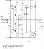
Upupa Epops is right!! ...the IRF 640 mosfets need temperature compensation...they only have negatif temperature coeficient above 6 Amps idle current
And 6 amps is a little to much!!!
Another point about the current fedback amp of Amp Man...it must not use a capacitor in paralel with the feedback resistor ( in your case the 1K resistor).Because in a current feedback amplifier the bandwidth and stability is dependent of the value of the feedback resistor.
Reply
Hey NETLIST If the IP address is same is because The guy named factor was using our computer in cyber cafe thats why everybody mistakes that amp_man_1 and factor are same guy
But i am amp_man_1 not factor
Hey Circlotron ,
I wasnt talking about the switching amps, all i said was through
the experienced gained by me in Linear CLASS-AB amps ,not in switching amps
In this amp the Mosfets are baised @ 200mA idle current with simple resistive biasing
Re: Reply
I just thought I recognized the word choice and layout of the posts. Good luck with your amp.
/Hugo
Don’t pay attention to my or others assumptions then.amp_man_1 said:But i am amp_man_1 not factor
I just thought I recognized the word choice and layout of the posts. Good luck with your amp.
/Hugo
Reply
ThanX TUBE DUDE for sugesstion on feedback cap!
I use Multi finned composite chamber aluminium heatsink and direct to surface forced fan cooling , to cool my amps.
IRF640 is rated at 150W and only have to dissipiate only 80 W of heat in worst case condition only.
I Think U all guys may not have a true professional experience with IRF MOSFETS for their Positive Temp. Coeff.
THATS why u all questioned about thermal runaway and current sharing in linear operation .
Use them as u like but i will use them acc. to my likes.
When i test the amp using square wave i apply the signal after the input capacitor.
This test insures that the amp is prematured and any component failure discrepencies are weeded out rapidly and thus it is ready for professional use.
An updated version will be released soon.
I am going to DELHI for 3 Days and may not available for the time being.
So i cant repond to queries for 2-3 days.
Re: Reply

If you drive an amp with a square wave and it swings rail to rail there will be very little dissipation in the output devices. They are either fully on or fully off. If you really want to stress it, drive it with a sine wave at about 2/3 full power. That is where the maximum dissipation is.
And that 150 watts is at a case temperature of 25 deg C. Downhill all the way after thatamp_man_1 said:IRF640 is rated at 150W and only have to dissipiate only 80 W of heat in worst case condition only.
If you drive an amp with a square wave and it swings rail to rail there will be very little dissipation in the output devices.
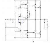
They are either fully on or fully off. If you really want to stress it, drive it with a sine wave at about 2/3 full power. That is where the maximum dissipation is.lumanauw said:Is this really current feedback? The front stage somehow resembles the Borbely design on "Mirrored Single Ended" and Hiraga amp. Both are not current feedback.
I may have missed something, but it certainly looks like current
feedback to me. The input is a class AB buffer, the buffer input
is the amp pos. input and the buffer output is the amp neg.
input. Any current flowing in the neg. input, ie. the buffer output
will caues an (almost) identical change in current over the
250 Ohm resistors, causing a voltage change which drives the
VAS.
- Status
- This old topic is closed. If you want to reopen this topic, contact a moderator using the "Report Post" button.
- Home
- Amplifiers
- Solid State
- True Current Feedback N-channel Mosfet Amp