Really ?????????????
Really Amp_man_1 !!!
It looks like you have no idea who you are up against !
Looks like you are looking out a 'very' tiny window. It's a HUGE WORLD outside . You seem to be missing it.
Take a moment and read other threads on this forum. It might be a revelation !
Cheers.
I Think U all guys may not have a true professional experience with IRF MOSFETS for their Positive Temp. Coeff.
Really Amp_man_1 !!!
It looks like you have no idea who you are up against !
Looks like you are looking out a 'very' tiny window. It's a HUGE WORLD outside . You seem to be missing it.
Take a moment and read other threads on this forum. It might be a revelation !
Cheers.
Amp_man_1 Revisited CFB amp
 "THIS VERSION IS DEDICATED TO CIRCLOTRON"
This my updated version which includes:
Input shunt resistor value inceased to 5.6k
IRFP240N is used at output now.
ceramic cap in feedback path is removed.
The dynamic Response Increases.

"THIS VERSION IS DEDICATED TO CIRCLOTRON"This my updated version which includes:
Input shunt resistor value inceased to 5.6k
IRFP240N is used at output now.
ceramic cap in feedback path is removed.
The dynamic Response Increases.
Attachments
Hi amp man
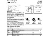
I think you might need to check your data on a IRF640. I have the IRF Data Book in front of me and it only has maximum case dissapation of 125 watts @ 25C minus a linear derating factor of 1W/Degrees C. It means if your device operates at a junction temperature of say 50 degrees C. The IRF640 in this case would have a rating of 100 watts.
Correct me if I'm wrong but I have calculated a maximum power dissapation across this device of approximatly 130 watts which happens at 160 watts into 4 Ohms, at 200 watts the dissipation drops to 125 Watts. I think you might need to review your data
and perhaps add one more pair of devices.
I to have been using IRF devices for many years and constructed amplifiers with power ratings up to 1600 watts into 2 Ohms.
I can tell you without thermal compensation in class A/B these devices will blow up, this is due to the negative temp, coefficent of the Gate threshold voltage verses temperature. As the drain current temp increases the gate threshold voltage decreases, increasing drain current which in turn increases temperature. I thing you might get the point.
This phenomenon gets worse as you approach 100 volt rails and beyond. the use of Source resistor helps control this problem by reducing the gain of the device, @ 50 volt rails you are not going to have a problem. but try this at 95 volt rails and add 100 to 200ma of bias current though each device as see how long your devices will last.
If you wish to read more on this goto the Advanced Power Technology site @ www.advancedpower.com It has some application notes and white papers on this very subject.
I hope this helps everyone including Ampman.
Regards
Anthony Holton
www.aussieamplifiers.com
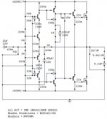
Circuit configuration.
I have been looking at this circuit and cannot see any current feedback.
I removed some components to make the circuit clearer
and added an opamp equivalent with regard to the feedback configuration to see what the feedback is really like.
It appears to be a standard voltage series feedback. There is no current sensing anywhere. The opamp version makes this very clear.
Cheers.
Attachments
Ashok,
your cleaned up schematic is either voltage feedback or current
feedback depending on if the op amp is voltage or current
feedback.
There is confusion about these terms, and people seem to
mean different things. Some people use the terms to denote
if the feedback senses the voltage over the load or the current
through the load, in which case this amplifier would certainly
be voltage feedback. This is also the way I learnt to use terms
from my ancient but excellent textbook Schilling&Belove, and
several other people seem to have learnt the same from other books.
However, it seems nowadays generally accepted to use these
terms in a different meaning, in the same way all op amp
manufacturers seem to use it. I had a very hard time to
understand the concept of current feedback amplifiers because
I had learnt a different meaning for the term and didn't realize
it is now often used for something completely different. Rather
than trying to explain here what current feedback means, let me
refer you to two excellent app. notes on this, Sloa21 from TI
and AN9520.1 from Intersil.
This is a confusion that pops up regularly in various threads.
On one occasion I suggested to use the terms voltage sense
and current sense for the "old" meanings of voltage and
current feedback. Nobody came up with anything better and
nobody seemed to have any literature references suggesting
"official modern" terms for this. I have though seen some
people use the terms voltage and current drive for these
concepts, which might be equally good or even better.
Feedback types
Hi Christer,
The opamp I have shown is supposed to be a standard voltage amplifying amp. V out= AxVin . The load current is not seen anywhere inside the feedback loop.
Negative feedback as we use it is taking a portion of the output voltage ( across the specified load ) or the current through the load and putting it in series or shunt with the input.
Here we have the voltage across the load that is taken for feedback. The load current , even inside the circuit , is not seen at the input in any form. In addition the sensed voltage is in series with the input signal , hence it is voltage series feedback.
Current feed back is quite clear I think. While it can be implemented in different ways I am sure , it is not seen in any form ( equivalent voltage or current ), at the input.
You can see the two load components at the output . The current through them is only passing thorugh the output devices and no part of it is seen anywhere at the input .
How can this be interpreted as voltage 'or' current feedback ?
I will look into those links. Thanks. Maybe someting new to learn.
Hope others come into the loop and clear up this 'confusion'.
Cheers.
Ashok,
you will see from those papers I referred to that current
feedback does indeed have quite a different meaning, at
least when op amp manufacturers use it. Happy reading,
but be prepared for quite a bit of confusion and frustration
for a while.
Note for instance, that if the op amp in your schematic were
a current feedback one, then the negative input would be
very low impedance and the output would not be proportional
to the voltage difference between the inputs, but to the
current flowing through the negative input. To add to the
confusion, the negative input is actually an output, from
a buffer whose input is the op amps positive input. So, the
load current has actually nothing to do with this concept of
current feedback.
CURRENT FEEDBACK ARGUEMENT
Mr. ASHOK u seems to me as a guy with NO understanding of current feedback topology.
U just showed that the opamp circuit is equal to my circuit by removing some transistors from it!
I just want to clear some doubts
Take a look at schematic!
1. IF differential pair is used at front end then the input signal and feedback signal are fed to the bases of transistors which result in change in voltage between the 2 base drives,
If we use the buffer input topology which i have used , then the input signal is fed into the bases of transistors but the feedback is fed to their emitters which result in current change but no voltage change in the transistor, in this way the part of output current is fed to emitters which inturns changes the curren flow and thus changes the drive also.
SO PLZ TAKE MY ADVICE READ SOME BOOKS & BRUSH UP UR KNOWLEDGE
Mr. ASHOK u seems to me as a guy with NO understanding of current feedback topology.
U just showed that the opamp circuit is equal to my circuit by removing some transistors from it!
I just want to clear some doubts
Take a look at schematic!
1. IF differential pair is used at front end then the input signal and feedback signal are fed to the bases of transistors which result in change in voltage between the 2 base drives,
If we use the buffer input topology which i have used , then the input signal is fed into the bases of transistors but the feedback is fed to their emitters which result in current change but no voltage change in the transistor, in this way the part of output current is fed to emitters which inturns changes the curren flow and thus changes the drive also.
SO PLZ TAKE MY ADVICE READ SOME BOOKS & BRUSH UP UR KNOWLEDGE amp_man_1
Please note that ashok is not really wrong, it is just that there
exists two different ways of using the terms voltage/current
feedback. Ashok uses it in the way it was tought in older
textbooks, it seems, and I am not so sure one could say
there is any general agreement on how to use the terms.
I have seen several people on the forum with very good
knowledge of amplifiers, including at least one commercial
manufacturer, use the terms in the same way as ashok.
however, since op amps are classified by the manufacturers
as voltage or current feedback in the same way as you and
most others use the terms, that seems the most reasonable
way to use them to avoid confusion. Or rather to minimize
the confusion for as many as possible.")
Please note that ashok is not really wrong, it is just that there
exists two different ways of using the terms voltage/current
feedback. Ashok uses it in the way it was tought in older
textbooks, it seems, and I am not so sure one could say
there is any general agreement on how to use the terms.
I have seen several people on the forum with very good
knowledge of amplifiers, including at least one commercial
manufacturer, use the terms in the same way as ashok.
however, since op amps are classified by the manufacturers
as voltage or current feedback in the same way as you and
most others use the terms, that seems the most reasonable
way to use them to avoid confusion. Or rather to minimize
the confusion for as many as possible.
amp_man_1,
you are missing the point. The confusion is whether current
feedback refers to sensing the current at the neg. input or
sensing the current through the load. The latter definition can
be found in textbooks, although it seems nowadays abandoned.
See for instance Schiiling & Belove: Electronic Circuits - discrete
and integrated, McGraw Hill, 1968, a book which defines the
terms in the same way as ashok and many others use them.
Terminology isn't always standardized, which causes confusion.
Another such confusion frequently causing discussion on this
forum is the definition of class B, which people also use in
different ways.
Then is it a Current Flow or Voltage flow?
Cripes !!! What are you getting at ?
This doesn't look like an intelligent discussion anymore!
Reply
OK MAN I will give u a little explanation of ur confusion.
The current feedback in my design doesnt refers to sensing the current through load instead it refers to the part of output current which is ERROR CURRENT, will be fed to emitters of transistors only to change the current drive characteristics of driveability of amp to load. This isn't any way states that the output voltage is sensed !.
Some old text books explains the CFB is taken through load.
Secondly , the magnitude of input signal current and error current differs a lot in CFB amp whereas the magnitude of input signal current and error current are in close match in Voltage feedback amps.THERE is large difference in magnitude of input and error current in CFB amps and in case of VFB amps the voltage across their +&- input remains equal to some exent.The voltage across inputs CFB amp has large difference between them.
- Status
- This old topic is closed. If you want to reopen this topic, contact a moderator using the "Report Post" button.
- Home
- Amplifiers
- Solid State
- True Current Feedback N-channel Mosfet Amp