Hello,
I will use the Coleman regulator in the near future.i asked him some questions before deciding to buy it when I am back home. From what I read so far it is clear that you need a minimum input to get the right output. But I think the problem is outside the regulator. ROD will answer here soon.greetings, eduard
I will use the Coleman regulator in the near future.i asked him some questions before deciding to buy it when I am back home. From what I read so far it is clear that you need a minimum input to get the right output. But I think the problem is outside the regulator. ROD will answer here soon.greetings, eduard
Yes indeed. The Ver. 7 requires less headroom than previous versions which were good at around 6v-7v headroom but even so, I'd suggest 5v. Rod will tell you.
Why not choke input? I'd be doing that with a big chunky 18v transformer without much voltage drop.
Hello,
I also think choke input is the way to go. Depending on the current you can use lundahl ll1694 or ll2733 both are so called filament chokes designed for higher currents. Not sure if an ordinary transformer will not saturate or will lack enough my for proper choke input.greetings, eduard
An other thing, with the Cole regulator and an output of 10volt
10V?
300B filament only 5V. The Version 7 works with 9V DC in.
10V?
300B filament only 5V. The Version 7 works with 9V DC in.
Sorry - replied in haste. You're right, 10v should be OK for a 5v filament. I'd still prefer choke input.
Oops, you are right10V?
300B filament only 5V. The Version 7 works with 9V DC in.

It's the 845 wih the 10volt
Mona
Yes, the TS has to find out why the transfomer voltage drops so dramaticaly with so little load.But I think the problem is outside the regulator. ROD will answer here soon.greetings, eduard
Mona
With a annouced 4A not even 1.3ASurely transformer don't have enough power.

Don't belive it's the transformer doing that.
Mona
Hi everyone,
I'm converting my raphaelite CSK30 to monoblocks and I wish to integrate the rod coleman regs V7 I assembled some months ago.
I'm in the testing phase and I encounter a strange behaviour, seems like not enough current is fed to the reg, witch seems odd.
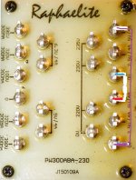
My PT is a PW300ABA-230 from raphaelite
390V - 320V - 100V - 0V - 320V - 390V at 300mA
5V at 4A (for the rectifier)
6.3V at 4A ( for common input pentode tubes)
2X 5V - 2.5V - 0V
I decided to wire the two 5V secondaries in serie to obtain 10V at 4A witch should be enough to feed the reg board.
An externally hosted image should be here but it was not working when we last tested it.
This is the way my secondaries are wired.
An externally hosted image should be here but it was not working when we last tested it.
This is the PSU I made on a breadboard.
R1 and R2 are 0R22 5W
The Coleman Reg R20=1K, Reg R1=0R82 5W
The Dummy res connected to reg output is 3R1 20W (10R 10W + 4R7 10W) that was all I had on hand to mimic a 300B.
The PSU gives 14.423V DC unloaded, so fine.
But as soon as I wire the reg board The Psu outputs 5.185V DC ??
Regboard output (with 3.1ohm dummy resistor) gives 2.71V DC
0.856A between PSU + output and regboard + input
the output does not seem to change much by altering the RV1 pot on the regboard.
Something is not working fine here. Rod asked to invert the phase of one of my secondaries, but I don't really know how to do this in my configuration.
Any clues?
Try attached pic.
Attachments
Felipe, this is "chinese" power.Try attached pic.
This power transformer described as "300VA" transformer, weight 5.6kg.
PW300ABA-230 300W Power Transformer (300B 2A3) | eBay
The total power (as the data table shows in post 1) 319.2VA.
If I want to provide about 300VA continuous, I choose at least 500-600VA core.
These EI cores weight are 8-10kg.
Well I tried with a new PT, an indel 2X9V at 2,22A in parallel so 9V at 4,44A
I also changed the diodes for 1N5822 and caps for Samwha HC 10000uf 35V.
i got exactly the same behavior
Here,s the full setup and numbers I found:
PSU Part:
R1= 33ohm 3W (that's the only 33R I got on hand)
C1 and C4 = Wima mks 220nf 63V
D1= 4x 1n5822
C2 and C3= Samwha HC 10000uf 35V
R2 and R3= 0,22ohm 5W
Reg Parts:
Q1 and Q6= BC546
Q2 and Q3= BC549 (not sure for Q3 as I cannot see the markings)
R1= 0,82ohm 5W
R20= 1K
R24= 33ohm
Dummy load= 4,7ohm 10W
Measures:
Mains= 231,6V AC RMS
PT out unloaded= 10,1V AC RMS
PSU out unloaded= 13,743V DC
PT out loaded (with RV1 fully anticlockwise)= 9,80V AC RMS
PT out loaded (with RV1 fully clockwise)= 9,76V AC RMS
PSU out loaded (with RV1 fully anticlockwise)= 4,380V DC
PSU out loaded (with RV1 fully clockwise)= 4,500V DC
Filament out (4,7ohm 10W load) with RV1 fully anticlockwise= 2,5V DC
Filament out (4,7ohm 10W load) with RV1 fully clockwise= 2,56V DC
Current PT out loaded= 0,671A AC
Current PSU out (+ wire) loaded= 0,5A DC
Current measures have been taken with a clamp meter on 2A caliber.
I don't get what's going on
I also changed the diodes for 1N5822 and caps for Samwha HC 10000uf 35V.
i got exactly the same behavior
Here,s the full setup and numbers I found:
PSU Part:
An externally hosted image should be here but it was not working when we last tested it.
R1= 33ohm 3W (that's the only 33R I got on hand)
C1 and C4 = Wima mks 220nf 63V
D1= 4x 1n5822
C2 and C3= Samwha HC 10000uf 35V
R2 and R3= 0,22ohm 5W
Reg Parts:
Q1 and Q6= BC546
Q2 and Q3= BC549 (not sure for Q3 as I cannot see the markings)
R1= 0,82ohm 5W
R20= 1K
R24= 33ohm
Dummy load= 4,7ohm 10W
Measures:
Mains= 231,6V AC RMS
PT out unloaded= 10,1V AC RMS
PSU out unloaded= 13,743V DC
PT out loaded (with RV1 fully anticlockwise)= 9,80V AC RMS
PT out loaded (with RV1 fully clockwise)= 9,76V AC RMS
PSU out loaded (with RV1 fully anticlockwise)= 4,380V DC
PSU out loaded (with RV1 fully clockwise)= 4,500V DC
Filament out (4,7ohm 10W load) with RV1 fully anticlockwise= 2,5V DC
Filament out (4,7ohm 10W load) with RV1 fully clockwise= 2,56V DC
Current PT out loaded= 0,671A AC
Current PSU out (+ wire) loaded= 0,5A DC
Current measures have been taken with a clamp meter on 2A caliber.
I don't get what's going on
Last edited:
You appear to dropping the voltage under load after the transformer. Are you sure R2 and R3 values are correct? What is the volt drop across each of them?
Voltage drop across R2/R3 (under load) is:
R2 (Positive Rail)= 121mV DC
R3 (Negative Rail)= -118mV DC
I checked their value, they are truly 0.22ohm
- Status
- This old topic is closed. If you want to reopen this topic, contact a moderator using the "Report Post" button.
- Home
- Amplifiers
- Tubes / Valves
- Trouble with Rod Coleman DHT reg