You can smoothly change the input voltage using of YELLOW indicator at the top of the chart.
Thanks again. This is such a great tool, and incredibly easy to use. Much respect!
--
Perhaps a far goal, but is it possible to consider more harmonics?
Maybe a weighted total of higher harmonics, or just H3.
Useful in PP operation..
OK. I'll increase the number of calculated harmonics in a few days.
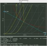
I am afraid that the problem is connected with the schematic diagram (wrong supply voltage - 250V), not with the triode simulator. It is impossible to have high supply voltage 250V, load resistance 2K5 and anode current 60mA. Look at the manufacturer anode characteristics od 2A3. When you have only 100V on the anode (250V - 60mA*2k5 = 100V) and bias voltage -45V the anode current is much more less than 60mA.
I thing that voltage 250V should be applied directly on the anode of 2A3 (point marked with 2 on the schematic diagram), and supply voltage should be around 400V (250V + 2K5*60mA = 400V). See the attached example.
The schematic isn´t wrong. The load specified is that of the reflected speaker through the transformer which corresponds to the AC loadline and pivots about the operating point (250V 60mA), while the DC loadline is an almost vertical line corresponding to the DC resistance of the output transformer (Because of this one can assume Vp=supply voltage)
Your program is excellent for designing resistance loaded stages, but in most cases it would not work for designing output stages due to the limit imposed on the plate voltage. Bear in mind that during half the cycle of a wave, the output stage will swing a voltage higher than the supply voltage due to the AC and DC loadlines being different.
An externally hosted image should be here but it was not working when we last tested it.
In the image, line A-B represents the AC loadline while line Vq-Q would represent the DC loadline for a transformer with 0 DC resistance (perfectly vertical), when the grid swings 15V negative from the operating point, the plate voltage becomes 300V which is more than the DC supply voltage of 250V.
Once you wrap your head around this concept I´m sure you´ll understand a lot of things that would otherwise not make sense.
I managed to get zero distortion!
Yes, you are absolutly right
") . This "phenomenon" results from the finite accuracy of graphic method of distortion calculation. This is not Fourier Transform !!!, but computer simulation of old method used by engineers half century ago. In simulator accuracy is much higher than in manual method, but still finite.
. This "phenomenon" results from the finite accuracy of graphic method of distortion calculation. This is not Fourier Transform !!!, but computer simulation of old method used by engineers half century ago. In simulator accuracy is much higher than in manual method, but still finite.In your example, lengths of sections used in the calculations are practically equal. This is evident even from the drawing. Therefore, almost zero distortion associated with the second harmonic. In fact, the graphical method of calculating distortions is associated with the cases that individual harmonics may even be negative (there are many examples in old books). No wonder that under certain conditions in the vicinity where the sign changes (- to + or + to -) the evaluated values are close to zero.
We all need to be aware that the results of graphical operations on the graph depend on the accuracy of the mapping of tube model. This is why I reccomend to verify presented tube characteristics.
Thank you again for above example
....
In the image, line A-B represents the AC loadline while line Vq-Q would represent the DC loadline for a transformer with 0 DC resistance (perfectly vertical), when the grid swings 15V negative from the operating point, the plate voltage becomes 300V which is more than the DC supply voltage of 250V.
Once you wrap your head around this concept I´m sure you´ll understand a lot of things that would otherwise not make sense.
Thank you for the reply. I am aware of the difference between AC and DC loadline in the case when the load is not pure resistance
. My remarks to the schematic diagram were made in the context of the simulation results and question asked by the user (the schematic is "wrong" in the context of the direct insertion of voltages and currents into the simulator - sorry if "wrong" statement has been received so.). Of course you're right about the anode voltage. I should not mix the supply voltage and the anode voltage.
Thank you again for your interest in the problem
.
Last edited:
for adding 6n16b.
Is it possible to use the applet on a Ipad?
I get now just a static picture in with i nothing can change.
This is not the aplet - it is javascript. In theory, should give a run on any web browser. I checked the behavior of the program in different browsers. There is no problem with new versions of browsers. Unfortunately, Internet Explorer version 8.0 and earlier can not cope with it. In a newer version of IE for example. 11.0 this problem does not occur. Users of WindowsXP using IE 8.0 wanting to take advantage of the program must therefore run it in a different browser than IE 8.0 (this is the highest version in Windows XP), eg using the Google Chrome or FireFox.
I can run the program on my tablet with Android system and on my smartphone. I don't know why it is not running on your device
. I don't know this device. Mayby your browser does not use "canvas" object or has different mouse event service. It is very important. You must check it in the documentation of Ipad.
Last edited:
The problem is because off the touchscreen device. Detecting the mouseover position is different. See also the link.
Modifying mouseover / hover events for iPad
I use Safari, Chrome and Terra browsers on the Ipad2 and 4 latest IOS, nothing works.
On my PC it works great.
Modifying mouseover / hover events for iPad
I use Safari, Chrome and Terra browsers on the Ipad2 and 4 latest IOS, nothing works.
On my PC it works great.
Last edited:
Hi,
Thanks for the addition.
If I may suggest the following popular types:
6N1P (USSR)
6Z32 (EF86) in triode mode
6S45P
6SL7 (or USRR equivalent 6N9)
6S3P (USSR)
TIA,
yep, 6n1p would be great.
it's about time something came that messed with the monopoly position of the TCJ software.

Great work gsmok! Thanks!
One question: the Uinp value of 1V is rms, right?
I think it would be very interesting to add harmonic distortion values for lower levels of Uinp, for example 10 mV rms and 100 mV rms. This would cover a wider range of applications (headphone amps, guitar amps etc). Would that be easy?
One question: the Uinp value of 1V is rms, right?
I think it would be very interesting to add harmonic distortion values for lower levels of Uinp, for example 10 mV rms and 100 mV rms. This would cover a wider range of applications (headphone amps, guitar amps etc).
Would that be easy?- Home
- Amplifiers
- Tubes / Valves
- Triode/Pentode Loadline Calculator