By all means, measure when its quiet, as well as not windy!
It helps if you measure with quite a loud pulse. I like it quite annoyingly loud, so long as it does not clip anything, especially the microphone. This improves your signal to noise ratio which is always an issue out doors. I cannot advise you on an LSPCAD level setting procedure, but you want higher line out or amp gain, and less line in gain. Always verify that the microphone is not clipping by recording a signal pulse and looking at it for fidelity in the time domain.
On the subject of resonances, I was not thinking of a panel resonance, but rather a cavity resonance. Your method with screws but no glue is common, I use it without issue in most cases. Your fingers will tell you if there are panel resonances....just feel around the panels while playing a sine wave at suspect frequencies.
A cavity resonance is a standing wave inside the box. These appear at the 1/4 wave distance of all three dimensions (L-W-H) to some extent or another, unless there are internal shapes to break them up. Curved and triangle shaped boxes are relatively immune in two of the dimensions, but the top to bottom will getcha!
You have to dampen these with stuffing. 10 mm padding is useful for a panel resonance, but won't do it for the cavity resonances. I like fibreglass. Dacron is OK if its the heavy long stranded type, but pillow stuffing doesn't seem to work very well. For a 65L enclosure, I would use about half a kilo or more, which is a fair bit. The Mid enclosure should be very heavily stuffed. Kudos for making it bigger than 3 litres, these always have issues. At 12 litres, you are looking at at least 200g....stuff it good. I expect this will make quite a difference.
Dick
Bigger than 3 litres? Hell, when I realised I was going to have to build big & deep cabs, I knew that the mid was going to get it's fair share as well ")
Actually, LspCAD showed that 12 litres allowed the HDS134 to roll off at 12db from 300hz so I went for it. I was going to try aperiodic with the mid but couldn't get the schematic to gel. C'est la vie.
I was going to try long fibre wool as we use it for insulation here in NZ--sheep to people ratio is 10:1--but I have some spare dacron so I'll shove some in the bass bin.
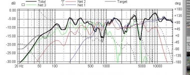
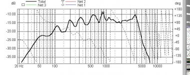
Latest data
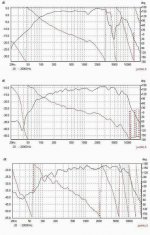
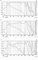
Measurement conditions as before: outside, speaker elevated 700mm, vertical and upside down. Mic on tweeter axis. All measurements on tweeter axis. Woofers measured individually.
This time I measured at 11pm when a lot quieter. I packed more dacron in the mid chamber to see how the response would change. Added dacron to the bass chamber to augment the foam carpet underlay on the walls.
Here's the combined response for all drivers. Woofers, green. Mid, red:
Attachments
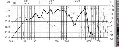
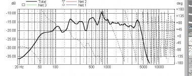
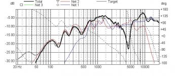
The lumpiness between 100hz and 1k in the mid seems to be reflected in the woofers. Surely that means baffle signature since the mid and woofers are in dissimilar chambers?
I have a second baffle that I can mount the mid in and see if without the box the lumpiness is still there.
I have a second baffle that I can mount the mid in and see if without the box the lumpiness is still there.
Bizzarro.........
On the whole, your data looks very good, except for the waviness in the lower mids. The stuffing should have made a very big difference, and it did not. I have never seen a baffle signature effect like that at these low frequencies.....its really rather pronounced isn't it? I tend to see diffraction artifacts in the 3-8 KHz range. The progression from near-far field showing the emergence is, IMHO, a smoking gun that these are baffle effects.
If this is the case, you of course simply ignore them. You can prove it to yourself by (ugh!) taking some more measurements. This time, you want to go off axis 10-30 degrees, and look for these waves to smooth out or disappear. If they ARE baffle effects, they should disappear off axis.
I confess, I have never seen this effect at these (low) frequencies before. The bad news is that this is weird. The good news is that you can safely ignore it in your design. The only other remote possibility bugging me is that this is an artifact in your setup. I'm not saying its so, but if you took a 5 dB p-p "sinusoid" with -15 dB amplitude, and mixed it with your measurements, it explains it too. Note how your close in measurements are at 0 ~ +5 dB levels, and would swamp a low level artifact. Further away, you are at -10 ~ -15 dB levels, and a noise signal would show up in thge measurements better. I would try lowering or increasing my measurement level to see if the waviness signature changes with signal level. If it does, you have a problem. If it doesn't, all is well.
The final possibility is that you have a reflection from something like a wall or the table, or the sky (just kidding). Ungated reflections show up as low level ripples that look like, well, this. Did you look at a pulse in the time domain to VERIFY that you can safely run your gates at 100 mSec?
Dick
Hi, Dick
Hmmm, so, you're thinking that I *may* have a spurious signal in my soundcard or amp? Any mains power would show at 50hz (NZ mains freq).
I'll try off-axis first cos that's easiest
Do you agree that the smoothness of the in-close measurements eliminates the cavity resonance possibility?
Re my 100ms gate: I just check that the impulse response is within the window and close to the left side. I assume this is correct. Actually, I may be confused on this. Can you clarify, please?
"Hmmm, so, you're thinking that I *may* have a spurious signal in my soundcard or amp? Any mains power would show at 50hz (NZ mains freq)."
Could be anything, mains is a likely place to start, but this doesn't look like it. I always try shorting my output to input whan I'm suspicious.....its amazing what flaws show up in cabling, sound cards, etc. The whole picture gives me a feeling that something is wrong....given that the same ripples show up in mid and woofer at frequenciers far too low to be edge diffraction.
"Do you agree that the smoothness of the in-close measurements eliminates the cavity resonance possibility?"
Yes. And I would have lost a bet on this aspect!
"Re my 100ms gate: I just check that the impulse response is within the window and close to the left side. I assume this is correct. Actually, I may be confused on this. Can you clarify, please?"
Try 25 mSec....we really don't care about 10 Hz anyway, and it will improve the signal to noise ratio some.
Too bad I do not know LSPCAD. When I set gates for indoor measurements, I run a pulse out through the speaker, and look at the return from the mic in the time domain. Here I see my noise floor (small ripple signals from zero to about 5 msec), my initial MLS burst, more ripples for another 5 msec, and an inverted, attenuated version of the MLS burst after that. This last piece is the reflection off the ceiling in my room. Its about 1/10 the size of the initial burst, but its very visible.
Indoors, the start gate is set just before the initial burst, and the stop gate is set just before the reflection. Now outdoors, you should not have the reflection showing up at all......just the MLS burst and NO reflections, allowing a long timed stop gate that gets you bass frequency resolution. My question was to verify that you did check a time domain return, and you did not see a reflection like you would see indoors. Next time you are indoors, try setting your stop gate PAST the reflection by a mSec or so just so you know what happens. This will bring a wicked ripple into your measurements at high frequencies....an artifact of the math being done by the computer.
Its all a bit irrelevent to the task at hand. I think you have enough data to do some design, but it would be very nice to know where that ripple is emanating from.
Yawn.....time for the sack........
Dick
Dick
I'm waiting on a new sound card to arrive before I can do any more measurements.
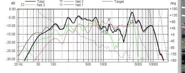
But, one question: if I'm sure that the sub 1k ripples in the response are not related to cavity resonances--which I am--is it legitimate to smooth the responses to remove the worst of the ripple? Then I'll have a legitimate trend that LspCAD can more easily work with during xo design.
I used the FRD Consortium's FRC tool to smooth my mid and tweeter responses, then viewed their combined response. It mirrored the unsmoothed combined response perfectly--as I expected--just without the wild ripples.
Any thoughts?
I'm waiting on a new sound card to arrive before I can do any more measurements.
But, one question: if I'm sure that the sub 1k ripples in the response are not related to cavity resonances--which I am--is it legitimate to smooth the responses to remove the worst of the ripple? Then I'll have a legitimate trend that LspCAD can more easily work with during xo design.
I used the FRD Consortium's FRC tool to smooth my mid and tweeter responses, then viewed their combined response. It mirrored the unsmoothed combined response perfectly--as I expected--just without the wild ripples.
Any thoughts?
You can smooth them if you like, but I would not. I would just ignore it, and "smooth by eye" during the crossover design. I would rather make the trade one way or the other myself, deliberately, than remove fidelity from data and have a smoothing algoritm do it mindlessly. The optimizer in my program will struggle with it, but thats OK, I never fiinsh with the optimizer result anyway.
Dick
Dick
- Status
- This old topic is closed. If you want to reopen this topic, contact a moderator using the "Report Post" button.
- Home
- Loudspeakers
- Multi-Way
- Treat twin woofers as one woofer?