Mos Fetish said:Actually, Matt, I've just gone and checked your suggested procedure on page 1 of this thread and you say to set the x and y position of the other drivers relative to the reference driver.
That's why I adjusted my mid by 130mm in the DY, because it's cone center is 130mm below the tweeter's, which was my reference axis for this measurement.
What am I misunderstanding?
The procedure I originally outlined, was taking into consideration that the drivers were all measured on axis. In other words the microphone was moved, up or down, left to right, but never forwards or back.
When you take these measurements they are all on axis and do not take into consideration any off axis behavior.
If you measure like this, in LspCAD, you set the mic distance the measurements were taken at and then alter the X and Y parameters. The software then alters the responses, using built in models, to account for the off axis response.
If you measure all the drivers on one axis, this is already taken into account, by the mic position and therefore, you leave the X and Y positions at 0,0.
I am guessing you knew this, its just with all the different things said here, some of it got lost along the way.
I wish I could do outside measurements, but unfortunately getting everything outside would be hard, nor do I have enough months without an R in either. I guess a cheap laptop + an all in one unit for measuring would be useful

70kgs isnt an easy load to position^>^ one wrong move and thats your back put out and im 22 so age doesnt seem to affect it. Wheres that forklift when you need it?

Dick, first of all, thanks for all your advice so far. I know these things can be frustrating.
Now, that chart.
That response has 1/6 octave smoothing applied to it, which is my standard setting. But if I use 1/12 or lower, it doesn't change that much. I was looking to show a trend.
Now, re the baffle step slope: from 500hz to 40hz it's shows a 6db attenuation. You're saying a should first see an 8db drop and then a 6db slope?
Ok, ground plane procedure.
I measure ALL drivers, both individually and combined, with the speaker elevated and tilted?
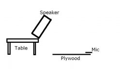
See attached setup plan.
So, I have a table outside. It's about 700mm high, higher than sawhorses. If I get my speaker up on that and tilt as much as I can, where do I position the mic? On the tweeter axis as per normal, or is there a more optimal position?
Now, that chart.
That response has 1/6 octave smoothing applied to it, which is my standard setting. But if I use 1/12 or lower, it doesn't change that much. I was looking to show a trend.
Now, re the baffle step slope: from 500hz to 40hz it's shows a 6db attenuation. You're saying a should first see an 8db drop and then a 6db slope?
Ok, ground plane procedure.
I measure ALL drivers, both individually and combined, with the speaker elevated and tilted?
See attached setup plan.
So, I have a table outside. It's about 700mm high, higher than sawhorses. If I get my speaker up on that and tilt as much as I can, where do I position the mic? On the tweeter axis as per normal, or is there a more optimal position?
Attachments
I don't know how to do all the fancy formatting this forum is capable of, but so be it........
"That response has 1/6 octave smoothing applied to it, which is my standard setting. But if I use 1/12 or lower, it doesn't change that much. I was looking to show a trend."
OK, that explains it. I don't generally use smoothing. It does show trends, but it hides artifacts that are sometime indicative of a problem....clipping a mic or sound card, funny resonance, etc.
"Now, re the baffle step slope: from 500hz to 40hz it's shows a 6db attenuation. You're saying a should first see an 8db drop and then a 6db slope?"
Nope, I think you have half a step. The step should start above 100 Hz on a 300 mm baffle....you said somewhere this was a 3 dB point, but thats not what I have observed on baffles this size. Below 100 Hz you are looking at your driver rolling off. The step starts about 150, and rises a total of 8 dB, to probably somewhere around 800 Hz, then settles back down to a 6 dB level at about 1000 Hz or so. The extra two dB from 750-900 bHz in my example, is an overshoot. Yours looks about like this except it peaks at 550 or so 4 dB up, and settles a bit further......to about 3 dB above the level where it was at 150. I could be wrong, but it just doesn't look right to me. Try the correct procedure, and see if it doesn't change.
"Ok, ground plane procedure.
I measure ALL drivers, both individually and combined, with the speaker elevated and tilted?"
Yes. Set it up one time, and take four measurements without adjusting anything at all except which driver(s) are getting power from the amp. No mic changes, level changes, movements, tilt adjustments, Z-positions........nothing. Holding your breathe helps too :^)
"See attached setup plan.
So, I have a table outside. It's about 700mm high, higher than sawhorses. If I get my speaker up on that and tilt as much as I can, where do I position the mic? On the tweeter axis as per normal, or is there a more optimal position?"
Your setup looks very good to me. Make sure your table is a table, and not a crate that has sides.........you want the speaker in 4-pi space, so the table should be minimal. I use a carpenter square against the baffle, and site along it to place the microphone. Standard design axis is precisely on tweeter axis, but I have learned that an inch above or below that is a good idea because some tweeters have nulls exactly on axis. You don't need a laser to site this.....just get it fairly close to the point on the ground where a line normal to the baffle would connect the tweeter and the microphone.
Dick
Great.
So, mic generally on axis of tweeter where it intersects with the plywood?
Am I correct in saying that the speaker needs to be elevated to avoid the boost in the bottom end that would result if it was on the ground?
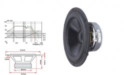
FWIW, attached is the manufacturer's chart for my woofer, Vifa M22.
Mos
So, mic generally on axis of tweeter where it intersects with the plywood?
Am I correct in saying that the speaker needs to be elevated to avoid the boost in the bottom end that would result if it was on the ground?
FWIW, attached is the manufacturer's chart for my woofer, Vifa M22.
Mos
Attachments
"So, mic generally on axis of tweeter where it intersects with the plywood?"
Yes
"Am I correct in saying that the speaker needs to be elevated to avoid the boost in the bottom end that would result if it was on the ground?"
I am going to equivocate on this point.....I am not sure why your measurement looks like it does, and a theory does not make a fact. The ones I have done well off the ground do not look like this. Perhaps if I had read Joe D's book on measuring, I would know.
"FWIW, attached is the manufacturer's chart for my woofer, Vifa M22."
I find the x-axis on that graph quite inscrutable. Why don't they just do it the way we all learned in engineering school? I have to guess, based upon a supposition that the Fs for the woofer is in the 30 Hz range......
Right on target: the M22 has an fs of 30hz.
What I was getting at re elevating the speaker and the boost in the bottom end was: I can assume that my measurements won't be boosted in the low end due to any ground effect? Cos having them ON the ground would give me a boost, correct?
What I was getting at re elevating the speaker and the boost in the bottom end was: I can assume that my measurements won't be boosted in the low end due to any ground effect? Cos having them ON the ground would give me a boost, correct?
Update:
I went through the harrowing experience of tilting my beloved 3-ways off a table secured only by a tow rope. The speaker and I survived. Unfortunately, I got less than useful measurements. They were almost as bad as measuring the low end normally.
I'm sure my setup was less than optimal, but my frustration was at maximum
So, after some consultation, I was inspired to use said table, and place the speaker upside down, and vertical, that is, woofers up. This placed the tweeter & mid at about the same height as they would have been normally but removed the ground effect from the woofer response. I measured on tweeter axis and noticed that it's top end was a little elevated, maybe due to ground effect or something. I can live with that.
I measured both woofers separately and the chart is attached.
I think it's looking good so far, but will measure again this weekend.
Only concern are the off-track anomalies (two dips, one peak) between 2.5k & 4.5 k, despite the track being perfect outside that range.
I did a t+m and combined comparison, which was spot on except for one massive dip at 5.5k (see next attachment), and a two woofer and combined woofers comparison, which was perfect (see next attachment).
I'm kicking myself for not doing a woofers/mid comparison as I'm sure that's where the error must be.
Experts, any thoughts?
Attachments
I do not understand what I am looking at
I have some basic, dumb questions before I offer a comment.
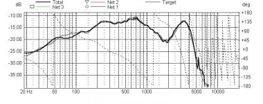
What were the exact test conditions for the three images? The first one is wide band, it looks like the drivers were all running.....this is fine. Are all four drivers active direct to the amplifier....no crossover components?? I would expect a measurement like that to look much worse than this one, the reason I ask.
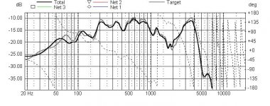
The second trace looks pretty good assuming a major phase issue between tweeter and mid at some point. This is common. The mid rolls off rather early, or is that a baffle step profile I see?
The final trace looks like what I would expect below 1000 Hz, we have a nice look at the baffle step. Its 1000-3000 that looks a bit off. These are the two woofers in parallel with no other
interactions?
Can you measure the mid and tweeter alone?
Dick
I have some basic, dumb questions before I offer a comment.
What were the exact test conditions for the three images? The first one is wide band, it looks like the drivers were all running.....this is fine. Are all four drivers active direct to the amplifier....no crossover components?? I would expect a measurement like that to look much worse than this one, the reason I ask.
The second trace looks pretty good assuming a major phase issue between tweeter and mid at some point. This is common. The mid rolls off rather early, or is that a baffle step profile I see?
The final trace looks like what I would expect below 1000 Hz, we have a nice look at the baffle step. Its 1000-3000 that looks a bit off. These are the two woofers in parallel with no other
interactions?
Can you measure the mid and tweeter alone?
Dick
Dick
I accidentally posted a severely smoothed chart.
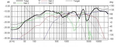
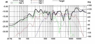
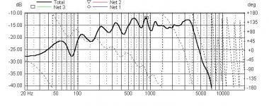
Attached here is a chart showing all drivers and the combined response. It's 1/6 smoothed.
It all matched up pretty well.
The mid would show some baffle step as I measured it with a 30ms gate.
Test conditions were as described:
Speaker upside down on table, so tweeter at bottom, about 800mm from ground. Mid higher still, and woofers highest.
The green trace is the woofers. They were measured individually and used as unit 1 & unit 2 in a parallel LspCAD configuration.
The combined trace is with all four drivers wired in parallel.
No components of course. Direct feed from amp.
I accidentally posted a severely smoothed chart.
Attached here is a chart showing all drivers and the combined response. It's 1/6 smoothed.
It all matched up pretty well.
The mid would show some baffle step as I measured it with a 30ms gate.
Test conditions were as described:
Speaker upside down on table, so tweeter at bottom, about 800mm from ground. Mid higher still, and woofers highest.
The green trace is the woofers. They were measured individually and used as unit 1 & unit 2 in a parallel LspCAD configuration.
The combined trace is with all four drivers wired in parallel.
No components of course. Direct feed from amp.
Attachments
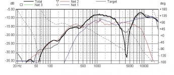
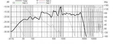
Here is just the woofer response.
Both woofers measured individually and then paralleled in LspCAD.
Combined trace with woofers in parallel. No components. Direct to amp.
That big return at 5k seems to mimic--although far more strongly--the manufacturer's response chart. Vifa says these woofers were optimised for bass reflex and suggest an fc of <500hz.
Attachments
M22 chart.
Well, maybe my response doesn't mimic it but there is a dip after 1k.
Perhaps the return at 5k is baffle edge defraction? If it's abnormal, what else could it be?
Both woofers are in same ported space, and both have almost identical response.
Well, maybe my response doesn't mimic it but there is a dip after 1k.
Perhaps the return at 5k is baffle edge defraction? If it's abnormal, what else could it be?
Both woofers are in same ported space, and both have almost identical response.
Attachments

Now you're getting somewhere.........
Nice data collection job. It all starts to make sense.
On the woofers. Your baffle step is, indeed, quite low down. If you ignore the peaks and valleys, its a perfect step starting at 150 up to about 600 give or take. The combined response all makes sense if you think about the fact that you have two drivers playing at 2 KHz.....they will interfere with each other like crazy, and a sequence of peaks and nulls will be sprayed into the sound field. Look at the phase response individually, and you will see it, obviously LSPCAD did!
You don't care about this too much, you will be crossing lower than the woofers care about. Below 500, they seem to add up pretty nicely, which is what you would expect. As an exercise for the student (or a guy with a tape measure), by knowing the distance to the microphone and the baffle angle, you could calculate the spacing between the woofers from this plot.....the two woofers are perfectly out of phase at 2000 or so, they are 1/2 wavelength apart from a distance viewpoint at this frequency.
Use the calculated combined response as a woofer when you design/optimize the crossover. The guck up high will not really figure into it because you will be a good 30 dB down before it matters. Your sims may show some weird behavior in 1-3 KHz, but just ignore it (it is an interference artifact) and try to get a good slope from 400-1000 where the data is sound.
The waviness in the woofers from 200-800 may be normal for these drivers, but possibly not. These are in the right place to be cavity resonances from within the box. You could try changing the stuffing by removing or adding, and see if these get better or worse. Beyond this concern, it looks like solid data to me, I would have predicted your step to be higher, but at this stage I believe your data!
As to the midrange, this looks a bit problematic. Again, I am inclined to believe the data, and this mystery mid is doing a nice broad rendering. You will have a problem in the crossover though.....the hole at 500 and the peak at 350 are smack in the middle of your crossover range. That one really looks like a cavity resonance in the box for the mid. Try a stuffing change or an angled piece of wood, and see if it moves around for you......I hope so, because this one looks like it might be audible.
The tweeter looks uninteresting, and that is a good thing.
Your next job, after checking out some stuffing changes, is to set the relative phases. I cannot really tell if you already did this or not since the idividual driver phases are suppressed in the chart. Get the three to add up to the composite shot, and then leave them alone from here on. Leave the mid at "0", and tweak the tweeter until they sum to your combined mid/tweeter plot. Then using that, adjustb the woofers in lock step until the woofers and mid/tweeter composite add up to the total composite.
After that, set the reference level that you will design the filters to. I would nominate -15 dB for all the target levels, which my quick look suggests is about 4 dB of BSC. You might like another level, but that is where I would start.
Nice Job.
Dick
Once again, Dick, thanks very much.
I want to come back to your post in a few days after I've measured again. You see, I live in a busy part of town that seems to get busier *just* as I set up my measurement gear So, I need to find a quiet time (late at night) and measure again, especially for the low end.
I get very good consistency on the stuff above 1k no matter how noisy the street is, but the stuff below 1k moves around a bit. The plots you see are generally the trend, but I want to make sure my data is as good as possible before I start chasing shadows.
Now, on the matter of cabinet resonances:
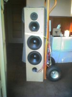
The baffle: my baffle is 36mm thick and NOT glued on to the speaker as yet. It is however secured by screws to the speaker and it's fairly snug since I put some window/door sealant foam strip between the baffle and the speaker. It's as air tight and rigid as I can make it... but I have been worried that it may show as a resonance in the plots. I haven't glued it because I'm not sure yet where I intend to site the crossover boards and I still want easy access to the box. If I have to I'll get my crossover plans sorted and glue it on.
Do you think this could be an issue?
Stuffing: the 65 liter bass enclosure is curved and only has 10mm carpet underlay foam--which is quite dense--lining it's walls. I thought that would be the best place to start.
The mid enclosure is 12 liters (Peerless HDS134) and is stuffed loosely with dacron.
Attached are some pics so you know what we're discussing.
Not great quality--from cellphone camera.
I want to come back to your post in a few days after I've measured again. You see, I live in a busy part of town that seems to get busier *just* as I set up my measurement gear
So, I need to find a quiet time (late at night) and measure again, especially for the low end.I get very good consistency on the stuff above 1k no matter how noisy the street is, but the stuff below 1k moves around a bit. The plots you see are generally the trend, but I want to make sure my data is as good as possible before I start chasing shadows.
Now, on the matter of cabinet resonances:
The baffle: my baffle is 36mm thick and NOT glued on to the speaker as yet. It is however secured by screws to the speaker and it's fairly snug since I put some window/door sealant foam strip between the baffle and the speaker. It's as air tight and rigid as I can make it... but I have been worried that it may show as a resonance in the plots. I haven't glued it because I'm not sure yet where I intend to site the crossover boards and I still want easy access to the box. If I have to I'll get my crossover plans sorted and glue it on.
Do you think this could be an issue?
Stuffing: the 65 liter bass enclosure is curved and only has 10mm carpet underlay foam--which is quite dense--lining it's walls. I thought that would be the best place to start.
The mid enclosure is 12 liters (Peerless HDS134) and is stuffed loosely with dacron.
Attached are some pics so you know what we're discussing.
Not great quality--from cellphone camera.
Attachments
- Status
- This old topic is closed. If you want to reopen this topic, contact a moderator using the "Report Post" button.
- Home
- Loudspeakers
- Multi-Way
- Treat twin woofers as one woofer?