Adding some DC resistance to the input voltage source might be advisable. As it stands the base of the input transistors are defined as 0.00 volts DC and that won't happen in practice.
Sorry, but I don't know how to do this.
Thanks... I kept reading what Calvin had written... it was the word "between" that confused (me)
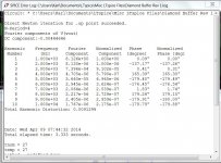
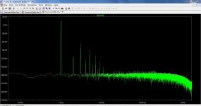
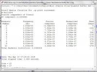
What is surprising in the simulation is just how much those added 47 ohms increase the distortion raising the figure to 0.12%
So, do you recommend leaving these resistors out all together?
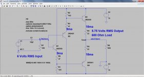
Yes, the voltage is approx. 16 volts peak to peak or 8 volts peak. That becomes slightly less than 6 volts rms (vpk/1.414). I set the input voltage to be 6 volts rms (8.5 volts peak) but the loading on the output pulls the level down. That shows the design has relatively poor drive ability. A good opamp would maintain the level with absolutely no change as it was loaded.
Assuming I put a volume pot in front of this buffer, why would you need to set the input voltage at such a high level(6 volts) when most sources output 2 volts or so?
I guess op-amps have there advantages, but I've never heard one that I liked when used as a buffer alone.
Sorry, but I don't know how to do this.
In the simulation the input voltage has "perfect" characteristics such as zero impedance, and at DC, it holds the base of the transistors to zero volts (ground) as if they were connected to ground via a piece of wire.
In practice (a real amp) you would probably AC couple the input and connect the bases to ground via say 10k to define the input impedance and DC conditions. That changes the performance slightly.
So, do you recommend leaving these resistors out all together?
Based on the simulation, yes. One thing I did notice was that the design is very dependant on the transistors used. I suspect that would translate to reality too. The currents in the first transistor were particularly variable with different devices, all other things being equal.
Assuming I put a volume pot in front of this buffer, why would you need to set the input voltage at such a high level(6 volts) when most sources output 2 volts or so?
I guess op-amps have there advantages, but I've never heard one that I liked when used as a buffer alone.
Normally it would be considered good design for an amp (buffer or not) to work well pretty much up to the point it clips. 2 volts rms is around 6 volts peak to peak.
Have you tried an LM4562 as a buffer ? I've been quietly evaluating these for the last few weeks and am finding them pretty much beyond reproach.
Okay, so the simulation is like the inputs being shorted to ground.
I didn't think about the differences between rms and peak to peak voltages.
No, I haven't tried the 4562 as a buffer. I've tried it in a couple of other applications and found the sound somewhat "sterile" personally.
I'll try it as a buffer, though.
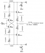
Shifting gears here a little...would the following buffer circuit from the Lehmann headphone amplifier have considerable more output current and drive, since it uses larger output transistors, vs. my initial circuit using TO-92 devices on the output?
You stated that my original circuit's output was being pulled down on your simulations, so I'm looking for a discrete BJT buffer that will maintain its output voltage better.
Oddly, this circuit also has 47 ohm resistors in series with the emitter of the BC devices.
I didn't think about the differences between rms and peak to peak voltages.
No, I haven't tried the 4562 as a buffer. I've tried it in a couple of other applications and found the sound somewhat "sterile" personally.
I'll try it as a buffer, though.
Shifting gears here a little...would the following buffer circuit from the Lehmann headphone amplifier have considerable more output current and drive, since it uses larger output transistors, vs. my initial circuit using TO-92 devices on the output?
You stated that my original circuit's output was being pulled down on your simulations, so I'm looking for a discrete BJT buffer that will maintain its output voltage better.
Oddly, this circuit also has 47 ohm resistors in series with the emitter of the BC devices.
Attachments
Hi,
the reason I suggested the 47R resistors at Q1/2s emitters in first place was that they were of convenient value and were there already.
From the choice of Q1/2s bias current and the emitter resistors the 22R output resistors values quite fell in place.
Of course could one choose all four emitter resistors lower in value, but that increases tolerance sensitivity of the circuit.
Also function the output emitter resistors as protective measurement against accidental short circuits, if either the ouput is shorted or one transistor fails, and it shields the output from capacicitive loading.
If the resistors are chosen small one would need one more resistor of 47R-470R in series with the output.
Still though if one output transistor fails it's shortcut could result in a breakdown of the second transistor too due to overpowering.
jauu
Calvin
Okay, so the simulation is like the inputs being shorted to ground.
I didn't think about the differences between rms and peak to peak voltages.
No, I haven't tried the 4562 as a buffer. I've tried it in a couple of other applications and found the sound somewhat "sterile" personally.
I'll try it as a buffer, though.
Shifting gears here a little...would the following buffer circuit from the Lehmann headphone amplifier have considerable more output current and drive, since it uses larger output transistors, vs. my initial circuit using TO-92 devices on the output?
You stated that my original circuit's output was being pulled down on your simulations, so I'm looking for a discrete BJT buffer that will maintain its output voltage better.
Oddly, this circuit also has 47 ohm resistors in series with the emitter of the BC devices.
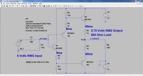
Here is your latest "Lehmann" circuit. Much better than the previous ones. I've marked the currents and voltages on the diagram and AC coupled the input. This hold up much better into 600 ohm loading. No simple buffer will give no change as loads are added because there is no global feedback to sense the amplitude error.
Attachments
Thank you for the latest simulation of the Lehmann circuit. I'll try building that circuit and see how it sounds. I'll have to order the BC and BD transistors from Mouser.
Also, when using the LM4562 as a buffer, is it better to use a 100 ohm resistor, from the output back to the inverted input, or just connect the two with a piece of wire?
I'm also using 100 ohm resistors in series with the inputs and a 49.9 ohm resistors in series with the outputs...Good idea, or not?
Thanks again...
Actually, the transistors you have (the 2N5550 and 2N5401) give pretty much identical results. If you increase the 10 ohms back to 22 ohm then the current is reduced slightly and well within limits for these devices. And remember this is all worst case into 600 ohm loading. Into the more typical 10 to 20k of a power amp things are better still. Try it with what you have first and see if you like it.
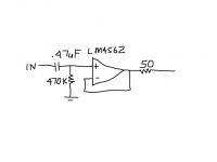
The 4562 is fine connected directly with no resistor. A series output resistor is often a good idea with opamps because the cable capacitance and input capacitance of the power amp is an unknown and can provoke really high frequency oscillation under some conditions. I would use a 0.47uf poly cap as an input coupler and a 470k from the opamp non-inverting input to ground to define the bias and DC conditions. There is no penalty with the high value because its shunted by whatever the source impedance is feeding it.
The 4562 is fine connected directly with no resistor. A series output resistor is often a good idea with opamps because the cable capacitance and input capacitance of the power amp is an unknown and can provoke really high frequency oscillation under some conditions. I would use a 0.47uf poly cap as an input coupler and a 470k from the opamp non-inverting input to ground to define the bias and DC conditions. There is no penalty with the high value because its shunted by whatever the source impedance is feeding it.
Attachments
- Status
- This old topic is closed. If you want to reopen this topic, contact a moderator using the "Report Post" button.
- Home
- Source & Line
- Analog Line Level
- Transistors in Buffer Circuit Running Too Hot