Posted by areza
the igbt is rated 27 a @ 25 c, its for prototyping , when I get everything under control I will replace them with rated one,
Should you not always consider current rating of an IGBT/MOSFET at 100/125 degree centigrade?
Hi
LOOOOOOOOOOL now you are loosing me
ok first if full-bridge, single 310v will be enough, next cooler the fets, transistors of anykind for that matter, can handle more current, so if 15A at 100C, then it will have more current at 25C without destruction, I think it was said 27A.
if you look at 27A x 310v that is 8.37kVA, but that is peak power, but that converter would be 4.2kVA, rms if you want...
I far as I know nobody said nothing about how powerful will be inverter, its not 1kw, not 5k, not 10k
He will tell us once he will know/or tell us...
Don't fight, lets all understand everything, so lets all try to Ask and Answer, ok?
PS areza: why don't you do FB?? I think you should
Ah if you go for that way, you heed 220v, yes and not 310Tahmid said:Luka,
I am going for square wave inverter. In square wave, RMS and peak voltage are the same. So, in the full bridge circuit, shouldn't I use approximately 220vdc to get 220vac out? Do I require 310vdc? If yes, why?
There will always be this, but not to worry,we will find common path...but for now try to stick to what you are doing now, not what you will, could you? So you will do HB, why not FB?areza said:its all mixed up, cos of linguistic barrier and everyone talking there kind of things and everyons voice mixed up, makes everyone misunderstand to everyone else, i was talking about my current project and future one, it was 2 deferent project and some basic theory.
i have no intention of overemphasize what i m doing or will do , some one just ask me about it so i replied, and all my post i was just answering things i asked for, may be some suggestion based on some real scenario, any way i don’t really want to argue with people and west all of our times , its just diying , so i m out of here,
Tahmid
What is the progress? Could you make 220v DC to 220v AC through Full Bridge Circuits? Do you require a circuit? If any sort of help require, we are there to help you. I will try utmost to help you. While making circuit, please use low ESR Capacitors because these Capacitors are the real culprit- failure of them is one of the main cause of circuit failure in high frequency application.
What is the progress? Could you make 220v DC to 220v AC through Full Bridge Circuits? Do you require a circuit? If any sort of help require, we are there to help you. I will try utmost to help you. While making circuit, please use low ESR Capacitors because these Capacitors are the real culprit- failure of them is one of the main cause of circuit failure in high frequency application.
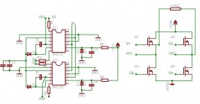
Here is the full bridge circuit. Hope that it is correct and that you will notify me of any errors.
Parts:
C1,C2,C3,C4 - 0.1uF 50V
C5,C6 - 4.7uF 50V non-polar
R1,R2,R3,R4 - 22 ohm
R5,R6 - 220 ohm
D1,D2 - 5V Zener Diode
D3,D4 - UF4007
IC1,IC2 - IR2110
Q1,Q2,Q3,Q4 - IRFP460
Input is given to pins where IN is written.
Parts:
C1,C2,C3,C4 - 0.1uF 50V
C5,C6 - 4.7uF 50V non-polar
R1,R2,R3,R4 - 22 ohm
R5,R6 - 220 ohm
D1,D2 - 5V Zener Diode
D3,D4 - UF4007
IC1,IC2 - IR2110
Q1,Q2,Q3,Q4 - IRFP460
Input is given to pins where IN is written.
Attachments
Some comments + questions.
1. If it is a square wave inverter, it is very simple indeed. Just make one 220Vdc rail and switch a Full-Bridge at 50Hz. By the way, you may also use simple opto-couplers for the upper FET's. More reliable and makes less damage, should the bridge fail.
2. If its a sine-wave converter, things get complex. There are several vays to go, 3 are very obvious:
A. Use a 20-50KHz class-D audio amplifier to create 24Vpp (from 12V battery) AC voltage. Use a simple iron trafo to rise that to 230Vrms. Nice, very safe way of doing things.
B. Use a sine-modulated Push-Pull or Bridge based PWM with HF (Ferrite) transformer to create a "rectified" sine waves with the correct amplitude. Use a synchronized low speed IGBT/MOSFET "inverting" bridge to transform the "rectified" full-wave sine to full-AC. Dont forget the antiparallel diodes on this slow bridge, that is, when using a IGBT's. A PIC18 uC can help you a lot, while going with PIC16F may be better, as it is so much simpler. Both PIC's can store a half-sine waveform in FLASH, creating an ANALOG sine reference for the PWM chips, or may themselves output a sine-modulated PWM. In second case, one have to know a bit on PID algorithms, otherwise he can expect a long and "interesting" (frustrating) time scratching his/her head in front of a black-burned pile of precious electronics, he just built.
And dont forget to add a discharger to the "rectified" wave, otherwise you get a very distorted sine on light loads.
C. Use an SMPS to do a +350V and a -350V rails, with a center tap. Use PWM modulation with optic drive to drive those IGBT's. Depending upon the PWM algorithm, you may need a 900V devices. But the sine wave will be better. The second algorithm may let you get away with 600V devices, but the sinewave will be more distorted on very complex loads.
Oh... and try to avoid those SG3525 controls when doing Push-Pull or a DC connected Full-Bridge. There is no way to insure correct flux balance in Voltage-Mode-Control. Watch it!
Question to Golam: what type of architecture an control you have used in PIC18F Inverter? What efficiency you could acheive? How long the project took? Did you used an on-chip PWM to make the sine? If yes, how many PWM bits were used? What THD did you get? What do you think is the real advantage for using a uC instead of cheap PWM chip?
hi Alexsch , i like to know about the topology you mention above , say for instance which one you would adopt if you want to build one ,
i like to know few more things,
1 . i believe the class d with iron core , can be scaled to 350v full bridge to eliminate the iron core, i m on the rite path ?
2. what do you mean by “add a discharger to the "rectified" wave “ ?
3. which topology would allow open loop or less complex loop control/feedback ?
4. wanna know your opinion on “ one of the MIC topology “ named as “DIRECT DC-AC INVERTION “ outlined as , pwm modulated sine wave feed into a isolated DC/AC converter , the content is retrieved through a set of low pass filter,
thanks in advance for your time.
Answer to Alexsch
My modalities for making sine wave inverter is conventional. First I made DC-DC Boost Circuit for converting 12/24/48 v dc to 310 v dc. Then I convert that into 220v pure sine wave through Hardware pwm through Pic Microcontroller and lastly demodulating the modulating frequencies(50 KHz) through LC Filter.
I also once made sine wave inverter with silicon core. Modalities were to apply the Modulating Pulse(6 KHz) and demodulate that frequency before the Transformer with LC Filter, so that Transformer see only 50 Hz and output also 50 Hz sine wave. I don't like Bulky Transformer and hence switched over to high frequency.
It took 1 year to develop the final one.
I used 18F1320 as it is having inbuilt mechanism known as ECCP. This Enhanced Pulse Width Modulation system is assigned 4 Pins for hardware PWM for Full Bridge Application. Yes I use this on chip pwm system. I developed a sine table, error correction table and feedback system to effectively carryout the instructions according to the table and ECCP Pins provide signal and corrected signal while it is running . This Pic can write /rewrite the program memory on the fly if proper program is written to do so. WDT rechecks the new rewritten table after each full cycle (20 mili second) and in case of extreme distortion, reset the controller.
Total pwm Bits are 256x4. for each full cycle- 20 mili second. Actual sine table is 256. The use is as follows:
256 bits from 0 to 255 from start to the peak for 1st quarter cycle, then 255 to 0 from peak to down- 1st half cycle complete. Next the same routine in the opposite phase to complete the next half cycle. So, 1 full cycle of 20 mili second is completed with only 256 bits actually.
With the help of ECCP, I turn on the 1 high side mosfet on and then provide pwm signal with 50 KHz to the lower one for half cycle and then turn off those 2 mosfets and turn on the other high side mosfet and provede pwm signal to the lower mosfet for next half cycle.You can not provide pwm signals to the upper mosfets. Rather they will be turned on for full half cycle alternatively and lower ones should be pwm-ed. The Cmos gate don't allow punch- throw, that is don't allow the upper and lower side mosfets of the same side to conduct simultaneously and prevents short circuit.
The efficiency is 89% and harmonic distortion is<7%.
I actually don't like to use discreet ics,if I can use micro controller. With Microcontroller you can do things which may require more than dozen discreet ics. You see, Pic 18F1320 is having internal 8 MHz oscillator, multichannel 10 Bit ADC, which can give you conversion result within 1.6 micro second, internal 2 Comparators with programmable internal voltage reference and you can toggle the output with program. 16 Bit Compare, 16 Bit Capture, Hardware PWM, single instruction cycle(with in 100 nano sec) add,subtract and multiplication capability, serial communication facility etc.etc. How many descreet ics require to ensure all this?
I use free MPLAB IDE of Microchip, PIc Microcontroller itseslf and the Programmer, made by me and I feel confident to do anything electronics. Any body, who does not know Microcontroller, it will be difficult for him to cope up with the trends of future electronics. This is the remark of the production in charge of a big Japanese electronics company-- right or wrong, I believe it.
With many many Thanks.
- Status
- This old topic is closed. If you want to reopen this topic, contact a moderator using the "Report Post" button.
- Home
- Amplifiers
- Power Supplies
- Transformer winding