Neglecting for the moment my usual lack of lucidity,No: the field increase that would be created by the secondary is exactly balanced by the one of opposite polarity the primary current generates....
 , if the fields of opposing polarity in the core cancel, exactly or closely, what causes the EMI which is normally observed near the transformer?
Well, that would be my guess too, but I think my small brain is at its limit again, since I have just been corrected above, to note:The magnetic field around the transformer comes from the uncancelled flux.
I am sort-of hoping we can show that Faraday's Law is a fallacy, or at least, that it does not apply to transformers. I hope my lucidity holds up that long, because I want to be present when it happens...the field increase that would be created by the secondary is exactly balanced by the one of opposite polarity the primary current generates.

If by EMI you mean the stray magnetic field, it is caused by leakage of the flux outside of the magnetic circuit. Some is caused by imperfect coupling and appears under load (and can be reduced with a flux band), but some is already present with only the primary connected. This part is caused by the finite relative permeability of the iron wrt to air. Note that the fact that some of the flux loops back through air does not necessarily means imperfect coupling.Neglecting for the moment my usual lack of lucidity,
More flux will escape in regions having a lower µr, ie those that are saturating or near saturation.
In a perfect transformer (coupling factor=1), the first mechanism of leakage is non-existent.
I think I meant elecromagnetic interference, which seems to be present in varying degrees, depending on the transformer, the shielding, etc. This would be caused by a magnetic field outside the transformer. Put a loop of wire or an antenna in range, and you have EMI. What I do not know, is whether this simply increases with the load, or with the "un-cancelled" magnetic field, or what else. Past experience with large-ish (not audio) transformers would seem to suggest that it goes up with load, but I have never tried to measure. Perhaps it increases with degree of saturation, or both. Your answer seems to suggest both.If by EMI you mean the stray magnetic field, it is caused by leakage of the flux outside of the magnetic circuit. Some is caused by imperfect coupling and appears under load (and can be reduced with a flux band), but some is already present with only the primary connected. This part is caused by the finite relative permeability of the iron wrt to air. Note that the fact that some of the flux loops back through air does not necessarily means imperfect coupling.
More flux will escape in regions having a lower µr, ie those that are saturating or near saturation.
In a perfect transformer (coupling factor=1), the first mechanism of leakage is non-existent.
Thanks AJT! And since the amplitude of the flux is determined by the primary voltage, the frequency and the primary turns, I suppose that this higher flux is again attributed to the fact that you can wind more primary. Am I right?
more primary turns means lesser magnetizing current and lower flux density and vice versa.....
more primary turns means lesser magnetizing current and lower flux density and vice versa.....
Well yes, for some reason I just thought I read this in my book.
Which of course states that flux just depends on number of turns. The answer then lies in the comment of Elvee, that higher quality cores can be used, so higher flux is implemented.another way of looking, with higher quality cores, you do not need more primary turns than when using lower quality cores....
when i build my traffos using surpluss/recycled cores, i assume that they are low quality ones and uses more primary turns...
another tip.....when using 230volt ac lines, i compute primary turns based on 260 to 280 volt ac lines, i get cool running trafffos this way...
when i build my traffos using surpluss/recycled cores, i assume that they are low quality ones and uses more primary turns...
another tip.....when using 230volt ac lines, i compute primary turns based on 260 to 280 volt ac lines, i get cool running trafffos this way...
You should define exactly what you mean: EMI implies waves, the stray field is... a field. These are quite different things, although in theory any variable field generates waves, but at low frequencies the effect is absolutely negligible.I think I meant elecromagnetic interference, which seems to be present in varying degrees, depending on the transformer, the shielding, etc. This would be caused by a magnetic field outside the transformer. Put a loop of wire or an antenna in range, and you have EMI.
You can detect the stray field with a loop, but normally not with an antenna, except perhaps in extreme circumstances.
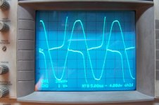
The picture below shows the V and I at the primary of a microwave oven.
When the current collapses suddenly after a deep saturation episode, a burst of RF energy is emitted, but this should not happen in a normally designed transformer where the only thing observable is a stray magnetic field having the two main components outlined above.
The no load stray field is likely to be heavily distorted, because it emanates from saturating regions of the core
Attachments
Yes, I could have defined that better.You should define exactly what you mean: EMI implies waves, the stray field is... a field. These are quite different things, although in theory any variable field generates waves, but at low frequencies the effect is absolutely negligible.
Using a typical small (<1KVA) power transformer as an example, and the definition you gave above, does the field increase when the load increases?
Last edited:
See #44.Using a typical small (<1KVA) power transformer as an example, and the definition you gave above, does the field increase when the load increases?
The part variable with the load does not primarily depend on the power, but rather on the geometry: a textbook transformer like the one you took as an illustration will show a huge increase in stray field with the load, but for a classical EI having superposed primary and secondary, the increase will be very modest. A modern EI with side by side windings will be worse, and a toroidal will be the best of all, provided it is wound properly, in a homogeneous manner
Yesterday, I used my 100VA toroidal transformer to perform some tests, and I accidentally short-circuited one of its windings. It's got 12 of them, so it requires careful attention to prevent all these wires from touching each other. Lesson learned.
I realised that I had done that, when I felt that these two wires were warm and saw some spikes across their ends. So I immediately took power off, and touched the transformer. It had gone hot, but not untouchable. I was able to put my hand on it for several seconds. It wasn't comfortably warm for a winter morning, but not untouchable either.
The fuse into the primary was a 0.63AT one, and it did not blow. That means that the power it drew can't be more than 145VA (230V mains).
So my question is, should I get worried about insulation getting stressed at all?
I realise that cores are typically able to run at 100 celcious as an upper limit, so my guess is that the accident fell within specs. Of course, such temperatures will not be repeated in future. I will also contact the manufacturer to know about its detailed limits.
If you had used the mains bulb tester it would have "lit up" instantly.
How often is this posted nowadays?
The T630mA fuse can pass double it's rated current for quite a long while and 4times rated for more than a couple of seconds.
Try a smaller fuse, maybe T500mA, or even F500mA, for closer rating.
I wonder if it would work using a T400mA fuse?
How often is this posted nowadays?
The T630mA fuse can pass double it's rated current for quite a long while and 4times rated for more than a couple of seconds.
Try a smaller fuse, maybe T500mA, or even F500mA, for closer rating.
I wonder if it would work using a T400mA fuse?
Last edited:
This is true, I will work on setting up a little box which will carry a bulb plus a fuseholder, to connect power transformers to mains safely.
Actually I will use a soft start and I was thinking about using 0.5AT. For my experiment, the only load to the toroidal's secondaries was a single 1200uF - 5.4R - 1200uF filter. That is why I did not bother about putting a larger fuse. I don't think that initial flux current could cause it to fail.
What about the insulation? Would it be any concern, since I was able to touch the trafo?
does it smell?
I did not smell anything when the fault happened, nor did I smell anything when I powered it up some minutes after.
- Status
- This old topic is closed. If you want to reopen this topic, contact a moderator using the "Report Post" button.
- Home
- Amplifiers
- Power Supplies
- Transformer operation