thanks guys. the amp i have a lacking in terms of transparency and also on highs. what could be the reason.
in the CSS design, ex: with the plate voltage and bias, it should have 80mA. we should using the CSS to limit it at 80mA? 90mA?
is it a good idea to limit it back to 60mA. for me CSS should not fix the current lower then what suppose to be the current at the bias point. it restric the tube to be functioning correctly. am i right?
Since completing my design I have increased the coupling cap to 4uf, though you could probably use a 2uf. I was getting resonance in the bass.
The things that will improve performance is to ensure that the triodes are sharing the current between themselves, this will require CCS's for each triode - not just each valve. Current balance in your output transformer is important but should be ensured by seperate CCS.
If you are using an interstage transformer, they require good current drive otherwise your top and bottom ends will suffer severly. I push 40mA through mine and I wouldn't consider much less.
Hope that helps.
Shoog
6080/6as7 SRPP
http://www.diyaudio.com/forums/showthread.php?postid=84773#post84773
The above link is an amp I am STILL very happy with. I up-graded to 5998. The 5998 needed the cathode resistors changed to 600ohm. The change gets about another 0.4 watts. This amp really does well on all types of music.
http://www.diyaudio.com/forums/showthread.php?postid=84773#post84773
The above link is an amp I am STILL very happy with. I up-graded to 5998. The 5998 needed the cathode resistors changed to 600ohm. The change gets about another 0.4 watts. This amp really does well on all types of music.
have anyone use the 6EM7 as the driver tube?
Looks like an excellent candidate for a partial feedback driver stage. Run the first stage at 4mA -1V bias. I have attached a schematic of how I used to do it.
Shoog
Attachments
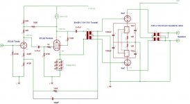
I use a mains toroidal as my interstage transformer and my output transformer.
The interstage is a 55V + 55V : 110V + 110V. The 55V windings are wired in series and the 110V windings are used as the phase split side. IN this way I get 1:1+1.
I use mains torodials as the outputs with the 6V secondaries as the output secondary.
These work well in this setup.
You need to post your schematic so that we can see if there are any problems with it.
Shoog
Yeah I know about the missing grid terminating resistor. I had to add a 1meg once I changed to real 6as7's. It did fine with late model Phillips 6080wa with floating grids though. I think I mentioned this on a later post on the referenced thread. As far as A2 operation I had an email once from some one accusing me of over-dissipation. All I can say is this amp has had flawless operation since 2002.coresta said:and how about the missing V3 grid resistor ?
Is your v3 runnig A2 ?

- Status
- This old topic is closed. If you want to reopen this topic, contact a moderator using the "Report Post" button.
- Home
- Amplifiers
- Tubes / Valves
- Transformer coupled 6AS7/6080