Shoog said:
This Allows you to use easily availble mains toroidals as output transformers.
What VA rating were the transformers you used ??
Andy
What VA rating were the transformers you used ??
For the outputs I used something about 120VA, but I have been assured that something around 30-50VA would do better.
For the interstagers I used what I could get which I think was 30VA or 50VA. In this position the smallest availble will be a destinct improvement.
if I were to use a regular output xformer, what should be the specs?
I think you would need something around 1K6. This might be very tough to source.
also that xformer in the middle, is that what you call an interstage?
Indeed it is, and it works very well.
any alternative to ecl82 in octal mounting?
Try looking at the range of TV deflection tubes. There are some that have dissimilar triodes in them that might work very well. The ECL86 is rated as a better tube, but is still 9pin.
The only thing you may have to tinker with is the two feedback resistors, all other values are accurate. I don't want to take mine apart to confirm the values.
For the power supply you will need silicon rectification as getting a valve rectifier to pass 300mA of current is not easy. You might get away with using a big 55V+55V toroidal for the power transformer. I used a Microwave oven transformer as a power supply choke (don't know how effective it is as an inductor, but it makes a nice big 50R resistor).
The whole motivation for this amp was to build a stereo PP amp with just 4 valves, it looks very well.
This will probably be one of the cheapest high end amps you could ever build. It runs in pure class "A" triode. Some of the most highly respected amps in the world use interstage transformers. It also has a differential output stage. If you can live with about 7watts then go for it.
Shoog
why toroidal?
also for the output transformers if the primaries is rated 115V, what should be the secondary rating?
also, what's the power rating of the amp? would it be suitable for 8ohm speakers?
can you please show the schematics of the power supply? I have seen designs where tube rectifiers where paralleled (thorsten's website). I think this allows greater amount of current to pass through.
thanks again.
Toroidals are cheap and they perform really well. The real motivation is because of where I live there is no readily availble source of "real" outputs without incurring huge postal costs.
The design requires 6V secondaries for 4Ohm speakers, and 9V with 8ohm speakers. Don't get to hung up on this, with such low output impedance the cgoice of output transformers is more forgiving than with most designs.
I can get 7watts per channel out of this baby, which is more than enough for me. This is about the theoretical maximum for this tube without going into AB class.
There is another 6080 amp on the web which uses toroidals but a more conventional valve phase splitter. It measures very well. It runs at a higher voltage - which may suit some people. Personally I think interstage transformers have been found to be the best phase splitters availble, though they do impose certain constraints on the design - namely the need for very low impedance high current drive.
Shoog
The power supply is very specific to the power transformer I had availble (a huge 1000VA toroidal), and the other bits I could cobble together. Using the PSU2 power supply design utility should allow you to create something to suit what you can lay your hands on. To be honest my exact design wouldn't be tremendously useful to you.
I really think that in this design the extra effort of using valve rectification isn't warranted. With resistance in the power supply chain, the result should be nearly identical. Using parallelled rectifiers presents risks because one valve is likely to hog the load and burn itself out. The way round this is to place resistance in the anode of the rectifier, but then we start to lose even more voltage than the waistfull rectifier itself.
Shoog
Hi Shooq,
Tks for sharing your 6as7-ecl82 schematic. I'm interested in building one and would like to know details of the CCS on the anode of the ecl82 pentode section.
Another question pls -- How is the interstage primary section connected in series or parallel (55+55V:110+110V)?
Thanks for your help.
Joe A
Tks for sharing your 6as7-ecl82 schematic. I'm interested in building one and would like to know details of the CCS on the anode of the ecl82 pentode section.
Another question pls -- How is the interstage primary section connected in series or parallel (55+55V:110+110V)?
Thanks for your help.
Joe A
Sorry for the delay in getting back to you.
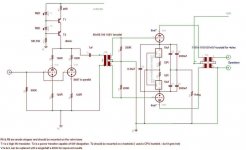
I have done a radical overhaul of the amp recently and have a new schematic. I dropped the ECL82 in favour of a parallelled 5687 which does a better job.
I have attached the new schematic with the specified CCS.
The interstage transformer goes with the secondaries wired in "series" as the primary.
I have done a radical overhaul of the amp recently and have a new schematic. I dropped the ECL82 in favour of a parallelled 5687 which does a better job.
I have attached the new schematic with the specified CCS.
The interstage transformer goes with the secondaries wired in "series" as the primary.
Attachments
Hi Shoog,
Thanks very much for your reply. That was sure quite a change. I was hoping to build mine with ECL86 front-end (because that's the closest I have in my box).
Are there any substitutes for the 5687 which you would recommend (ecc82/88 or octal) without componentry changes. (You see I'm not good at designing circuits, I mainly copy them.)
Also what type of transistors do you use in your CCS? Naming them would make it easier to select the correct ones.
Thanks for your help
Joe A
Thanks very much for your reply. That was sure quite a change. I was hoping to build mine with ECL86 front-end (because that's the closest I have in my box).
Are there any substitutes for the 5687 which you would recommend (ecc82/88 or octal) without componentry changes. (You see I'm not good at designing circuits, I mainly copy them.)
You could use the original circuit with the ECL86, and I believe it would be an improvement on the ECL82. The reason I went over to the 5687 is because the feedback constituted to high a percentage of the plate current of the triode section. This was swamping its natural response. Reducing the feedback resulted in the triode overloading at low input voltages.
The 5687 is a simpler option which has plenty of headroom and can handle the required current. There are no reasonable substitutions apart from the 6H30p which will cost more than the 5687. Before I went to the 5687 I used the pentode (triode strapped) of the ECL82 at 40mA which worked well, but struggled to give the required gain. Married to a high gain preamp you could probably use the ECL86 in the same way - but this seems a terrible waste.
Also what type of transistors do you use in your CCS? Naming them would make it easier to select the correct ones.
I used pulls from an old computer monitor. I couldn't tell you the exact numbers and the only relevant spec is voltage compliance. 200V for the bottom one, and anything over 30V for the top one which should be high gain.
Hope that helps.
Will be away on holiday for a fortnight so wont be able to answer any more questions.
Shoog
dear all,
i need your help. i have asked someone to build me a parallel push push amp using the 6080WC tube. it is on monoblock with each block have 4 unit 6080 tube on each block. it is transformer coupled with 6EM7 as the driver tube.
at the begining, i faced the problem on unconsistant bias current and my friend has change to CCS using the LM317 chip to fix the bias for each tube at 80 mA with B+ 225V.
howver, the problem i faced now is the amp is running extremely hot. hot on the power, ouput and interstage transformer.
my friend told me that it is common for this tube and design. i have used EL34 before but doesn't face this problem.
can anyone advise and help whether the it is normal for the 6080 tube amp to be that hot.
many thanks.
")
i need your help. i have asked someone to build me a parallel push push amp using the 6080WC tube. it is on monoblock with each block have 4 unit 6080 tube on each block. it is transformer coupled with 6EM7 as the driver tube.
at the begining, i faced the problem on unconsistant bias current and my friend has change to CCS using the LM317 chip to fix the bias for each tube at 80 mA with B+ 225V.
howver, the problem i faced now is the amp is running extremely hot. hot on the power, ouput and interstage transformer.
my friend told me that it is common for this tube and design. i have used EL34 before but doesn't face this problem.
can anyone advise and help whether the it is normal for the 6080 tube amp to be that hot.
many thanks.
I run my 6080's at 100V plate to cathode and 100mA current. I calculate the plate dissipation to be (100x0.1) 10watts. The max plate dissipation is stated as 13W per triode.
You are running yours at nearly twice that (though you don't state the actual plate to cathode voltage). The point been that running your valves this hard will probably kill them quickly.
The reason everything is running hot is because the air around the valves just can't move the heat away quickly enough. Other components will start to die quickly as well.
LM317 CCS make good bias components.
Shoog
many thanks. the 100mA current is per tube or per triode?
mine plate to cathode is 225V with 80mA per tube. i measure the 1 ohm resistor across the across one tube. grid to cathode is 135V.
i read from one of the datasheet that the plate voltage can be 250V with 80mA. as the link below
http://www.bmm-electronics.com/Product.asp?Product_ID=229
can you help to share whether the design got any problem? can you share your schematics?
many thanks.
cjng74 said:many thanks. the 100mA current is per tube or per triode?
mine plate to cathode is 225V with 80mA per tube. i measure the 1 ohm resistor across the across one tube. grid to cathode is 135V.
i read from one of the datasheet that the plate voltage can be 250V with 80mA. as the link below
http://www.bmm-electronics.com/Product.asp?Product_ID=229
can you help to share whether the design got any problem? can you share your schematics?
many thanks.
250 volts by 80 mA result in (250 * 0.08) 20W per section while maximum allowed is 15W.
IMHO,this tube gives best results when used at lower voltage and more current.
Don't go over 150V, and 100mA.
I consider that as an absolute limit !
Use adequate power supply and load impedance as for exemple:

Yves.
The 6080 spec sheet say 13W dissipation. By choosing any point over this you preclude the possability of dropping in substitutions.
I calculate your dissipation at (225*0.08) 18W.
Running them at 100V by 100mA gives 10W dissipation. It is sensible to run valves at about 20-30% below ratings to help prolong there life. I get about a year of service out of mine with them running nearly 20hrs per day.
The fact that you have so many valves on the one case only makes things worse. This is because each of the valves is heating the others - so your actual dissipation may be much higher. I would anticipate a service life of a few months at most.
Since I also consider that this valve sounds better at Higher currents I would strongly advise re-jigging the circuit to run your valves at 100V and 100mA or to run them at 200V and 50mA, with the former been my prefered option.
These are pass regulator valves and the datasheet describes a different set of operating condition than normal amplifier service - it can mislead.
Shoog
I calculate your dissipation at (225*0.08) 18W.
Running them at 100V by 100mA gives 10W dissipation. It is sensible to run valves at about 20-30% below ratings to help prolong there life. I get about a year of service out of mine with them running nearly 20hrs per day.
The fact that you have so many valves on the one case only makes things worse. This is because each of the valves is heating the others - so your actual dissipation may be much higher. I would anticipate a service life of a few months at most.
IMHO,this tube gives best results when used at lower voltage and more current.
Since I also consider that this valve sounds better at Higher currents I would strongly advise re-jigging the circuit to run your valves at 100V and 100mA or to run them at 200V and 50mA, with the former been my prefered option.
These are pass regulator valves and the datasheet describes a different set of operating condition than normal amplifier service - it can mislead.
Shoog
thanks. the 100mA is for one triode or per tube (2 diode)?
in my amp, it is per tube because the 1 ohm resistor is connected in serial to the other cathode.
if 225V with 40mA per triode then it is 9w. is my understanding correct?
high voltage or high current draw is prefer for the 6080 tubes (225V Vs 100V)? thanks again.
in my amp, it is per tube because the 1 ohm resistor is connected in serial to the other cathode.
if 225V with 40mA per triode then it is 9w. is my understanding correct?
high voltage or high current draw is prefer for the 6080 tubes (225V Vs 100V)? thanks again.
if 225V with 40mA per triode then it is 9w. is my understanding correct?
Sorry for the misunderstanding. My description is for each triode. It seems you are in spec. Your description was a little confusing.
All triodes work best at higher currents- it linearises them, the 6080 family more so as it starts out as a not to linear triode.
If you look at the curves you will see that the lines are starting to bunch up as the voltage rises. Also by going to higher voltages you place huge demands on the driver stage - which is also likely to start distorting itself, especially when you consider how hard the 6080 is to drive. My bias point is -30V which is a breeze to design a driver around.
Thirdly a low impedance output transformer will perform much better than a high impedance output transformer .
Unfortunately it is probably a little late to make the adjustments to your circuit.
Shoog
Hi Shoog:
I believe your 6080 PP is a lot similar the Seth 2A3 PP in the Magnequest forum.
But yours is CCS balanced.
And has cheapest iron and tubes.
Very nice schema.
Best regards Jaime
http://www.magnequest.com/diy_lessard_circuit_2a3pp.htm
I believe your 6080 PP is a lot similar the Seth 2A3 PP in the Magnequest forum.
But yours is CCS balanced.
And has cheapest iron and tubes.
Very nice schema.
Best regards Jaime
http://www.magnequest.com/diy_lessard_circuit_2a3pp.htm
- Status
- This old topic is closed. If you want to reopen this topic, contact a moderator using the "Report Post" button.
- Home
- Amplifiers
- Tubes / Valves
- Transformer coupled 6AS7/6080