tada!
Ive been pretty bussy with my bike racing and my job so I havent been able to post for a while, but here is a pic of my new center channel.
center channel
Ive been pretty bussy with my bike racing and my job so I havent been able to post for a while, but here is a pic of my new center channel.
center channel
Yeah, its your design. I made it from Red Oak Veneered plywood and I went over all the sides with a 45 degree roundover bit. It was finished with a natural oil finish (i think). At first I was really dissapointed with it. Then I realized that I had not turned on surround sound and only the sub + 2 mains where on.... After I turned it on, it sounded fantastic.
An externally hosted image should be here but it was not working when we last tested it.
this one had less stuffing in it, and it suffers from a slight dip in the upper frequencies. An externally hosted image should be here but it was not working when we last tested it.
This one had more stuffing in it and the dip is gone.

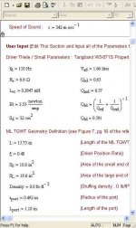
In a recent thread Will asked for the dimensions of "my" pipe and looking at it I stumbled over the driver position.
Usually non-tapered ML-TL´s end up with a driver ratio of 0.33-0.36 (seen so in GM´s designs) for least ripple and taking care of the third harmonic.
Further simulations even confirmed that a driver position around 1/3 is optimal (in comparison with tapered ones where it moves more to 1/2)
In case of the TB-pipe you see a driver ratio of 0.48 which gives a nice graph in the SPL-window and only a little peak/dip at around 900Hz which should be rather inoffensive.
Is the driver ratio now optimal or not?
TIA
Hi Joensd,Is the driver ratio now optimal or not?
those things happen, if the blind is leading the lame
I can´t recollect in detail, what I tried when simulating the Tangband. But I am pretty sure that I did the 0.33 ratio too. Maybe I arrived at about 0.48, because my FF 85K pipe has that ratio. And THAT design is by GM
Rudolf
In case of the TB-pipe you see a driver ratio of 0.48 which gives a nice graph in the SPL-window and only a little peak/dip at around 900Hz which should be rather inoffensive.
Is the driver ratio now optimal or not?
Yes, and no (maybe). You found the point that ~completely suppresses the 3rd harmonic, but doen't lower the 5th any, which theoretically is the more audible of the two. I've never done exhaustive comparison testing to determine any potentially audible differences, so as always YMMV. Anyway, I calc 0.4006, which supresses both somewhat, though more on the 3rd and the one I would use in this pipe.
Regardless, the sim loses accuracy as frequency increases due to the way MJK programmed it (vent and driver output emanates from the same point), and why I prefer to stick with the calc'd position as I've found it works well enough and I don't have to do any simming to prove it to myself.
BTW, the referenced pipe dims shows the vent diameter as 0.492", but based on your '70Hz' comment would make it the radius. Also, using the specs I originally got from CSS, I get a misaligned driver/pipe with a sag in the response beginning around 200Hz down to a peaking Fb. With these specs, a damped 0.75" long vent is required to get a ~flat response.
So what specs did you use, and are they considered to be ~accurate?
GM
Many thanks Rudolf&GM for clearing that one.
There´s obviously less "rules" than I thought.
The dimensions in post4 have an error as the diameter stated is actually the radius. For less confusions I just attached the pic of the sim. Specs are published numbers so....
There´s obviously less "rules" than I thought.
The dimensions in post4 have an error as the diameter stated is actually the radius. For less confusions I just attached the pic of the sim. Specs are published numbers so....
Attachments
- Status
- This old topic is closed. If you want to reopen this topic, contact a moderator using the "Report Post" button.
- Home
- Loudspeakers
- Multi-Way
- TQWT for the TB W3-871S