isnt that what the drawing shows??This would place the driver on the opposite side for a rear port
joensd: what did you do in the way of stuffing, I think im going to build your design today... then try out other designs after i get the drivers in the mail.
Hi Chris,joensd: what did you do in the way of stuffing, I think im going to build your design today... then try out other designs after i get the drivers in the mail.
as said I just finished one (second at the latest tomorrow) and they are still not played in. I haven´t played much with stuffing and that´ll probably take some time as this is my first vented project and TL-alike.
As the enclosures are relatively small and MDF is cheap you won´t regret having tried it and certainly won´t spend a fortune.
You can still finetune the design if you like more bass and don´t play them too loud and adding a sub I believe this will be a very "mature" setup.
I can supply you with the matchcad-sheet if you wanna fool around with that yourself.
And certainly let me know how it goes.
Cheers
Jens
Chris8sirhC said:isnt that what the drawing shows??
No, I'm suggesting the driver be moved to the opposite side, and the port tube to the side opposite it. Then shorten the tapered end of the pipe so the port tube goes under it. This should allow the driver to be placed at 13". There's an example drawing on John Rutter's TQWT Calculator. http://melhuish.org/audio/software.html
I used .25 lbs stuffing per cubic foot to start.
@chris8sirhC
What I have learned frrom the Masters (GM, correct me if I am wrong") ) and what has worked for me:
) and what has worked for me:
I distribute the stuffing with the predetermined density from the bottom of the driver up to the top (throat) of the enclosure. At the bottom of the driver just enough stuffing to prevent higher frequencies from escaping through the vent.
what did you do in the way of stuffing ...
What I have learned frrom the Masters (GM, correct me if I am wrong
) and what has worked for me:I distribute the stuffing with the predetermined density from the bottom of the driver up to the top (throat) of the enclosure. At the bottom of the driver just enough stuffing to prevent higher frequencies from escaping through the vent.
Thanks Rudolf for the stuffing advice.I distribute the stuffing with the predetermined density from the bottom of the driver up to the top (throat) of the enclosure.
This will save me screwing about the whole weekend.
But does the driver have enough air to breath with that much stuffing in the back?
BTW: The CD is on its way. Drop you a mail soon. Have a nice weekend.
i did a quick search and nothing came up, but how do you find a port that is say .9'' or 1.18'' in diamater??? The only think i could really come up with is to drilll the hole for the port to go into, then cut a toilet paper roll vertically, roll it over itself untill you come up with the right diamater to fit into the hole, then cut off the excess and put glue it into the port hole after you trim it to the right length. Is there a better way?
Update
Again it´s supposed to be a straight QWT, how much of that I really managed I can´t tell as I still have no measuring equipment for a fr-plot.
I simulated with Martin King´s worksheets at a average driver position of 0.4 and finally placed them at 0.2 and 0.6.
I also simulated both specific positions which looked okay in themselves.
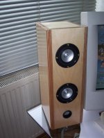
In comparison with the former QWT I brew up with only one driver these play with MUCH more authority in the bass and very nice as well that you have two point sources now which improves "dispersion" and so give a much better stereo feel.
Lenght again is 40cm, area is 16*12*cm^2
Radius of the port is 1.6cm, lenght 1.8cm position at 35cm.
I really do like the sound of them but have the feel they have slight bump around 100Hz which I will hopefully measure soon.
A notch filter is still to come.
Regards
Jens
Again it´s supposed to be a straight QWT, how much of that I really managed I can´t tell as I still have no measuring equipment for a fr-plot.
I simulated with Martin King´s worksheets at a average driver position of 0.4 and finally placed them at 0.2 and 0.6.
I also simulated both specific positions which looked okay in themselves.
In comparison with the former QWT I brew up with only one driver these play with MUCH more authority in the bass and very nice as well that you have two point sources now which improves "dispersion" and so give a much better stereo feel.
Lenght again is 40cm, area is 16*12*cm^2
Radius of the port is 1.6cm, lenght 1.8cm position at 35cm.
I really do like the sound of them but have the feel they have slight bump around 100Hz which I will hopefully measure soon.
A notch filter is still to come.
Regards
Jens
Attachments
My gut reaction is that the lower driver would effectively kill the quarter-wave action of the tube by introducing frequencies higher than those presented by the upper driver in that portion of the tube (I hope that makes sense). That may be the cause of the lower bass response.
Still being quite a newbie theory-wise all I know is basically from Martin´s site and the twodriver.pdf.
So simulating with an average position, looking at both plots alone and see if they "add up" correctly.
Of course any bumps would add up as well which make a noth eventually more needed.
But where´s my mistake now?
How to you tackle 2-driver QWT´s else then?
So simulating with an average position, looking at both plots alone and see if they "add up" correctly.
Of course any bumps would add up as well which make a noth eventually more needed.
But where´s my mistake now?
How to you tackle 2-driver QWT´s else then?
Ok, I'll try. In order to get bass extension from the cabinet the upper frequencies get "stacked up" in the upper portion of the cabinet while the lower frequencies "stack-up" near the port. Positioning the driver helps suppress the third-order harmonics. If you place a driver low in the cabinet you're introducing the frequencies that you don't want at the port. I think you either need to place the drivers as close together as possible on the front baffle or make the speaker a bipole with both drivers the same distance from the top of the cabinet.
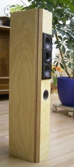
Another (untapered) QWT with two drivers
When I calculated my small ML-QWTs with d´Appolito units, I used the position of the tweeter as the reference point. Nearfield measurements of the unit and the port showed a good enough compliance with the Martin King worksheets.
Please note that the QWT terminates just below the port. Length of the line is 16", total height of the enclosure is 28".
Regarding Jens´ Tangband loudspeakers:
I would second Timn8ter´s advice to "make the speaker a bipole with both drivers the same distance from the top of the cabinet". I can´t imagine the constellation as presented in the picture to work as a real ML-QWT. And I see strong lobing at the higher frequencies.
BTW: Beautiful finish of the woodwork, Jens!
Attachments
Timn8ter said:or make the speaker a bipole with both drivers the same distance from the top of the cabinet
That was my immediate thot...
i see you safely made it home, how were the gardens?
dave
>Positioning the driver helps suppress the third-order harmonics. If you place a driver low in the cabinet you're introducing the frequencies that you don't want at the port. I think you either need to place the drivers as close together as possible on the front baffle or make the speaker a bipole with both drivers the same distance from the top of the cabinet.
====
Correct, find the point where the 3rd harmonic is suppressed and use it as the acoustic center of however many drivers is to be used, which should be placed as close together as physically possible. Now what the pipe 'feels' is a virtual ~rectangular driver. Ditto with an MTM except the tweeter is positioned at the acoustic center, and as you surmised, pipe loading is severely compromised if it's a short line, effectively making it acoustically a BR.
GM
Thanks everybody for the insight and critiques.
Just shows that I like to put things together before reading up enough. ;-)
Anyway had a lot of fun with them, smelled some "real wood" after a MDF-period (birch ply) and actually really do like the sound of them.
Without any notch they don´t sound as boomy as the other variant and even the sealed version whilst providing more bass.
I kind of understand that the bipole variant would be the preferred but theoretically : what would have made my attempt more succesfull?
Just moving the drivers closer together?
At least now I got another project even without thinking about it. (when I´m finished listening to those)
edit: just writing too slow. thanks GM
Just shows that I like to put things together before reading up enough. ;-)
Anyway had a lot of fun with them, smelled some "real wood" after a MDF-period (birch ply) and actually really do like the sound of them.
Without any notch they don´t sound as boomy as the other variant and even the sealed version whilst providing more bass.
I kind of understand that the bipole variant would be the preferred but theoretically : what would have made my attempt more succesfull?
Just moving the drivers closer together?
At least now I got another project even without thinking about it.
(when I´m finished listening to those)edit: just writing too slow. thanks GM
planet10 said:
That was my immediate thot...
i see you safely made it home, how were the gardens?
dave
Safe and sound. We had a great time, thanks!
(one hour wait at the border
)- Status
- This old topic is closed. If you want to reopen this topic, contact a moderator using the "Report Post" button.
- Home
- Loudspeakers
- Multi-Way
- TQWT for the TB W3-871S