minor update, i made the pinheader a 2x3 pinheader, this is still combatible with 3 pin design but you need to clip the excess pins or solder just a 3 pin
i made this since i design my own regulator and "base board" i might as well improve the connection...
the current base board looks like this:


i made this since i design my own regulator and "base board" i might as well improve the connection...
the current base board looks like this:

My recommendation is to use low esr tantalum caps, and c0g 0.1uf to aditionally reduce esr. I know DS says x7r and x5r are acceptable, but they loose a lot of capacitance if not grossly overspeced, which now starts to get quite big for small pcbs, and you still risk oscillations with them, especially on such small area where you cannot get the proper layout. Another thing though, don't expect performance to be as stated on the datasheet, again too small of an area to obtain best results. As for design, i'd loose trough hole pins and use smd jumpers, where you can just apply blogs of solder and connect pads. Save on space = make better layout.
you mean like lose capacitance over time?My recommendation is to use low esr tantalum caps, and c0g 0.1uf to aditionally reduce esr. I know DS says x7r and x5r are acceptable, but they loose a lot of capacitance if not grossly overspeced
i was wondering if i could make it sound better with WIMA and electrolytics, and there are also some chinese board using tantalum
why is that? i placed all capacitors as close as possible to the pin, i wouldnt be able to place them closer even with a bigger layout, you just cant really count the row of 5 resistors since they are 5x 10uF to get to the datasheet recommended 47uF while lowering ESRAnother thing though, don't expect performance to be as stated on the datasheet, again too small of an area to obtain best results.
not sure why LDVOR only uses 4x10uF but i added a fifth one
tho i was wondering about if the voltage settings line could pick up more noise if they are longer
i kinda designed it around best power in/out layout, the voltage settings lines i squeezed in kinda afterwards
definitely a bit true, i just went for a more userfriendly voltage setting, its definitely preference here but the design can be improved with smaller padsAs for design, i'd loose trough hole pins and use smd jumpers, where you can just apply blogs of solder and connect pads. Save on space = make better layout.
X7R and X5R loose capacitance when voltage and heat applied. Quite dramatically if their V rating is not way beyond derated. Some cases over 70% of capacitance, so your regulator doesn't have 50uF on output for example, but 20uF.you mean like lose capacitance over time?
If it were as easy as that... Circuit impedance is very important for these kind of regulators. Best is to use planes instead of traces, you risk LC tank circuit, which brings oscilations. And you haven't prepared for it with a pad for tant that has ~300mOhm esr on input to prevent that. Fingers crossed that it doesn't happen. You must look this design under oscilloscope when you print and solder it. Usually it's best to make a design as similar as possible to the wanted end result, but add pads for all kind of passives you may require since it's an smd design, and it's quite hard to rewire, add components etc..why is that?
hmm and this is not calcuclated already into the recommended values? i kinda thought its hard to go wrong with the datasheet reocmmendation, after all they probably evaluated the design with the recommended values/parts, no?X7R and X5R loose capacitance when voltage and heat applied. Quite dramatically if their V rating is not way beyond derated. Some cases over 70% of capacitance, so your regulator doesn't have 50uF on output for example, but 20uF.
do you have something to read on multiple planes designs? im still kinda unsure how i should design a 4 layer boardIf it were as easy as that... Circuit impedance is very important for these kind of regulators. Best is to use planes instead of traces, you risk LC tank circuit, which brings oscilations. And you haven't prepared for it with a pad for tant that has ~300mOhm esr on input to prevent that. Fingers crossed that it doesn't happen. You must look this design under oscilloscope when you print and solder it. Usually it's best to make a design as similar as possible to the wanted end result, but add pads for all kind of passives you may require since it's an smd design, and it's quite hard to rewire, add components etc..
i was also thinking of getting a cheap-ish ocilloscope, or atleast measure with a ADC the performance of the circuits (as long its possible with a ADC), to atleast detect bad design
A Picoscope 2204/2205 works well for this sort of testing. An audio interface will have a low pass filter set at about 22k so you won't be able to see anything happening at higher frequencies.
I also use REW and a Behringer UAC222 which is low cost and works at 44 and 48Khz sample rates, with 2v RMS in and out.
I also use REW and a Behringer UAC222 which is low cost and works at 44 and 48Khz sample rates, with 2v RMS in and out.
You would be surprised how much datasheets can miss/forget to include stuff. One big thing for 4701 is that they missed the 10nf cff cap to minimize noise as much as possible, aith feedback resistors. Yes they said use x7r and x5r, but have not mentioned appropriate voltage derate. Thats up to the designer to know his stuff. As i said above, it will loose a lot of capacitance, and you've placed small footprint which to me say you used 50V caps as bom which is not enough. I wouldn't use below 100V for x7r and x5r for maximum output of your reg. Also note that datasheet says 50uf for stability, you won't have nearly as much. Thats why i said use low esr tantalum and 0.1uf cog, that will be low enough esr and you won't have caps that are piezoelectric as a bonus.hmm and this is not calcuclated already into the recommended values? i kinda thought its hard to go wrong with the datasheet reocmmendation, after all they probably evaluated the design with the recommended values/parts, no?
I meant planes on top plane in a two layer pcb. Using vias is not recommended for such ldo's.do you have something to read on multiple planes designs? im still kinda unsure how i should design a 4 layer board
i was also thinking of getting a cheap-ish ocilloscope, or atleast measure with a ADC the performance of the circuits (as long its possible with a ADC), to atleast detect bad design
But yes, in general start learning to design stuff with multiple layers, much better designs can be made in general, which are hard to put on a two layer board. My advise is read up on altium education material, and watch altium seminars, live and recorded.
how would you rate this one? only the input goes trough vias, i guess i dont need to route it around the connector at the edge there, i will shorten the input trace
i exchanged all cog caps to 100V, added a 1uF cog at the output + 120uF panasonic SEPF 35V
would you still recommend placing many vias to connect both ground planes on both layers?
Also note that datasheet says 50uf for stability,
i guess with tolerances you have to actually do 47uF and calculate the possible tolerance of the cap, so in reality it probably is a 56 or 58uF cap (if you dont calculate in cog as you say)Yes they said use x7r and x5r, but have not mentioned appropriate voltage derate. Thats up to the designer to know his stuff.
i kinda thought they account for that but maybe the uF values are absolute measured
Well i used now a 120uF panasonic SEPC, because they seem one of the best electrolytics but LCSC dont have all values in stock...
the cog resistors are X7R 100V now, LDVOR actually just uses 25V ones.. i copied the bom before
tho its unclear for me if the 1uF bypass cap on the output is really enough to get to specs again... since X7R are the lowest ESR caps i dont know how electrolytics+bypass cap change things compared to COG only
10uf c0g is imposible 😁 probably x7r. C0g is a very low value cap, mostly highest used is 0.1uf. But there are a bit larger, though at bigger foootprint and much higher price.
Last i recall sepc had top V value of 16V. Be careful there with how much vout you set on regulator. Also using smd components, reduces parasitics that may influence stability of your regulator. I'd use 47uf low esr tantalum with 0.1uf. But you are free to use whatever you please, but do get a scope, and check stability once you make it, under load of course.
Last i recall sepc had top V value of 16V. Be careful there with how much vout you set on regulator. Also using smd components, reduces parasitics that may influence stability of your regulator. I'd use 47uf low esr tantalum with 0.1uf. But you are free to use whatever you please, but do get a scope, and check stability once you make it, under load of course.
Chapter 8.2.2.1 in datasheet clearly mentions derating.Yes they said use x7r and x5r, but have not mentioned appropriate voltage derate.
Attachments
ahh, sorry i thought you just mean ceramics (MLCC) but its either X7R or C0G10uf c0g is imposible 😁 probably x7r. C0g is a very low value cap, mostly highest used is 0.1uf. But there are a bit larger, though at bigger foootprint and much higher price.
should i use C0G preferably for bypassing?
i switched the 1uF X7R output bypass cap with a 0,1uF C0G one
i guess i will use a 20uF X7R then for input and keep the 1uF for noise reduction as the datasheet recommends
ah you might be right, i picked SEPF 35V, sorryLast i recall sepc had top V value of 16V. Be careful there with how much vout you set on regulator.
Did you already experiment with this regulator? or is this more of a general recommendation? tho i might as well go with it, i dont have that much expierenceI'd use 47uf low esr tantalum with 0.1uf. But you are free to use whatever you please, but do get a scope, and check stability once you make it, under load of course.
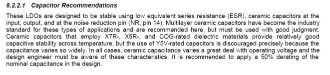
is derating 50% like this: datasheet mentions 47uF, you take 50% and put it on top? so 68uF would be the more appropiate real world value for output?Chapter 8.2.2.1 in datasheet clearly mentions derating.
Edit: oh i think its about the voltage... so better use double the max voltage for capacitors
Missed that. Still 50% for class 2 is too little. Definitely not gonna be 50uf with that.Chapter 8.2.2.1 in datasheet clearly mentions derating.
@Ghoostknight yes, use 0.1uf c0g if you use tantalums or elcos. No need if you end up using mlcc.
Yes, it is a part of my latest design. There also have been people that have made more detailed measurements with tants vs mlcc on tps regs.
It is about voltage and 50% is too little especially for X5R. I have tested some 22uF 25/35V X5R capacitors which had about 30% capacitance left at 15V.is derating 50% like this: datasheet mentions 47uF, you take 50% and put it on top? so 68uF would be the more appropiate real world value for output?
Edit: oh i think its about the voltage... so better use double the max voltage for capacitors
One option is to use Panasonic hybrid polymer caps:
https://na.industrial.panasonic.com...rid-aluminum-electrolytic-capacitor/series/80
voltage limit seems to be the limitation of tants, is 35V here fine? personally i probably wont use them above 15V@Ghoostknight yes, use 0.1uf c0g if you use tantalums or elcos. No need if you end up using mlcc.
Yes, it is a part of my latest design. There also have been people that have made more detailed measurements with tants vs mlcc on tps regs.
also, what about the input 10uF cap, tant or mlcc? currently its X7R
i choose 2x33uF at 35v tant with 0,06ohm ESR ( https://www.lcsc.com/product-detail/Tantalum-Capacitors_KEMET-T521D336M035ATE065_C696815.html ), there is not a big catalog at lcsc.com so i went with two for the output caps, it should be even better because of half ESR, i dont think the 19uF matter that much, it accounts for tolerances a bit i guess
- Home
- Design & Build
- Electronic Design
- TPS74A700 Regulator Board