Hi Waly,<nitpick>
That would provide a sufficient condition for stability. That is, it is possible to have an unstable inner loop, and the amplifier to be globally stable.
The most direct method of assessing stability of multi loop systems is to compute the eigen values of the closed loop system matrix. Other than in very simple cases, this is not practical in audio circuits because the poles are often widely separated and the order of the system can also be quite high.
Probably the easiest method in the frequency domain is the procedure called "sequential loop closures", or "sequential return differences":
1. Open all loops such that the resulting system is stable.
2. Assess the loop gain of one loop with all other loops open. Keep track of the number of clockwise encirclements of the Nyquist point.
3. Close that loop and assess the loop gain of the next loop. Keep track of the net number of encirclements of the Nyquist point.
4. Close that loop and do the same for the next loop.
5. Repeat for all loops.
At the end, if the net number of encirclements (clockwise - counter clockwise) equals zero, the system is stable. If the net number is greater than zero, the system is unstable.
This procedure is mathematically exact, however it has one practical shortcoming: it is hard to identify a single phase margin and/or gain margin. You could take the minimum phase margin and minimum gain margin as assessed for each loop, but then you may get different numbers if you select a different evaluation sequence.
Note that assessing one loop while other loop(s) are closed is rigorously wrong. It leads to a case of circular logic: when analyzing loop A, you don't know if loop B (closed) has a RHP. If it would, then loop A has to encircle the Nyquist point exactly once (counter clockwise) to make the overall system stable. That would be equivalent to say that loop A is stable because loop B is stable, and loop B is stable because loop A is stable.
</nitpick>
could you please provide a pointer to a place -- probably a good book -- where one can read more about the procedures you described?
Thanks in advance and best regards,
Matthias
EDIT:
Sorry, just saw your subsequent mail. But anyway, where does this stem from?
BR, Matthias
Last edited:
Stability of 'pure Cherry'
However, the amps in post #4 and #58 are very close to 'real life' stuff I tried circa 1990 and are most certainly stable .. even with funky loads, overload, bla bla ..")
They certainly don't need shunt capacitance on the VAS collector .. which as you rightly point out .. is truly evil. In fact, even TMC or TPC networks sully the Holy HiZ heretical nature of that point and IMHO, are nearly as evil
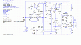
If its OK with you, I'll use the amp from #58 (which is just #4 with C1/3 150p and C9 470p. I've moved the Tian probe to the base of Q12, the VAS input, like Michael suggests, so we can look at the inner 'pure Cherry' loop.
This is Cherry.gif. Remember, this is something which is known to work well in real life.
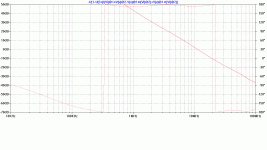
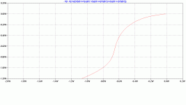
First we short the VAS emitter resistor R22 out to get noR22.gif We see the phase toodles along and crosses the 180 line on either side of the 0dB freq. so its almost certain this amp is unstable. .TRANS confirms this ... as does real life.
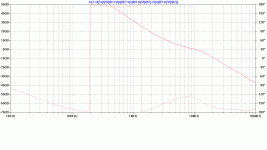
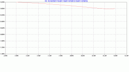
Next we restore R22 to 22 to get R22.gif The phase still does it's high wire act around 180 as before .. BUT .. as it nears the 0dB, it rises so that the 'Phase Margin' is some 50 degrees.
Michael, thanks for the LTspice models. I'll need some time to work on them as they have 5 active devices in the forward path of the minor loop and may not be amenable to 'pure Cherry'.The TIS emitter resistor does not significantly alter the instability of the OIC minor loop as I've demonstrated above. Send me your email address.
However, the amps in post #4 and #58 are very close to 'real life' stuff I tried circa 1990 and are most certainly stable .. even with funky loads, overload, bla bla ..
They certainly don't need shunt capacitance on the VAS collector .. which as you rightly point out .. is truly evil. In fact, even TMC or TPC networks sully the Holy HiZ heretical nature of that point and IMHO, are nearly as evil
If its OK with you, I'll use the amp from #58 (which is just #4 with C1/3 150p and C9 470p. I've moved the Tian probe to the base of Q12, the VAS input, like Michael suggests, so we can look at the inner 'pure Cherry' loop.
This is Cherry.gif. Remember, this is something which is known to work well in real life.
First we short the VAS emitter resistor R22 out to get noR22.gif We see the phase toodles along and crosses the 180 line on either side of the 0dB freq. so its almost certain this amp is unstable. .TRANS confirms this ... as does real life.
Next we restore R22 to 22 to get R22.gif The phase still does it's high wire act around 180 as before .. BUT .. as it nears the 0dB, it rises so that the 'Phase Margin' is some 50 degrees.
Attachments
'pure Cherry' stability II
"But what about the 'Gain Margin?" you might ask. It's 180 @ 1.2MHz where the gain is 26dB.
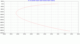
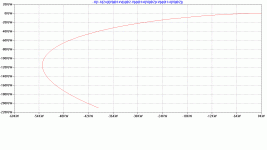
To answer this, we need to look at the true 'linear' test of stability, the Nyquist plot. (see eg bob-cordells-power-amplifier-book post #2761) These are NyquistNoR22.gif & NyquistR22.gif But both of these plots converge on (0, 0) from 180 so must be unstable .. or are they?
Both indeed move across the 180 line .. BUT ITS WHAT HAPPENS WHEN THE PLOT NEARS (-1, 0) which is important. To see this, we have to expand the area near the origin by a zillion times.
ExpNyquistNoR22.gif shows that the plot indeed encircles (-1,0) Without R22, the amp is unstable.
ExpNyquistR22.gif shows that R22 has kinked the Nyquist plot so that it no longer encircles (-1, 0). The amplifier is stable according to this 'linear' model ... and also according to .TRANS with various loads ... and most important of all, it is stable in 'real life'.
But please download the .ASC files and models from posts #4 & 5 and try for yourself.
Its very instructive to look at Nyquist plots with different magnifications. Shows very clearly what dem Phase & Gain margins are ... and why excursions across 180 far from (-1, 0) dun matter ... and wat dis 'conditional stability' is .. and what happens with different loads ...
BTW, this is just the inner 'pure Cherry' loop cos Michael wanted to look at that. The outer loop is also stable with various loads bla bla as you might have guessed from post #4.
I hope to get Michael's 'Triples + Supa VAS' stable with 'pure Cherry' too but need to overcome my fear & trepidation
Those versed in the art will realise I've sorta cheated as I use one other stability dodge in this example which is not obvious to the unwashed masses ... but I've mentioned elsewhere, cos I don't use ALL of Prof Cherry's dodges. Mea maxima culpa. But the point is .. it IS possible to use 'pure Cherry' to obtain excellent performance, ie better than evil TPC & TMC, with very simple circuits without compromising stability. This post argues, Prof Cherry's most important stability dodge.
"But what about the 'Gain Margin?" you might ask. It's 180 @ 1.2MHz where the gain is 26dB.
To answer this, we need to look at the true 'linear' test of stability, the Nyquist plot. (see eg bob-cordells-power-amplifier-book post #2761) These are NyquistNoR22.gif & NyquistR22.gif But both of these plots converge on (0, 0) from 180 so must be unstable .. or are they?
Both indeed move across the 180 line .. BUT ITS WHAT HAPPENS WHEN THE PLOT NEARS (-1, 0) which is important. To see this, we have to expand the area near the origin by a zillion times.
ExpNyquistNoR22.gif shows that the plot indeed encircles (-1,0) Without R22, the amp is unstable.
ExpNyquistR22.gif shows that R22 has kinked the Nyquist plot so that it no longer encircles (-1, 0). The amplifier is stable according to this 'linear' model ... and also according to .TRANS with various loads ... and most important of all, it is stable in 'real life'.
But please download the .ASC files and models from posts #4 & 5 and try for yourself.
Its very instructive to look at Nyquist plots with different magnifications. Shows very clearly what dem Phase & Gain margins are ... and why excursions across 180 far from (-1, 0) dun matter ... and wat dis 'conditional stability' is .. and what happens with different loads ...
BTW, this is just the inner 'pure Cherry' loop cos Michael wanted to look at that. The outer loop is also stable with various loads bla bla as you might have guessed from post #4.
I hope to get Michael's 'Triples + Supa VAS' stable with 'pure Cherry' too but need to overcome my fear & trepidation
Those versed in the art will realise I've sorta cheated as I use one other stability dodge in this example which is not obvious to the unwashed masses ... but I've mentioned elsewhere, cos I don't use ALL of Prof Cherry's dodges. Mea maxima culpa. But the point is .. it IS possible to use 'pure Cherry' to obtain excellent performance, ie better than evil TPC & TMC, with very simple circuits without compromising stability. This post argues, Prof Cherry's most important stability dodge.
Attachments
unstable inner loop and stable outer loop?
A sensible example if possible ... but a stupid one will do if there are no sensible amp circuits which behave like this.
Waly, could you post a case/circuit where an inner loop is unstable but the final device with encompassing loop is stable? The TPC mid peak dun count cos it is NOT unstable (2nd order); only likely to be highly strung.Waly said:Note that assessing one loop while other loop(s) are closed is rigorously wrong. It leads to a case of circular logic: when analyzing loop A, you don't know if loop B (closed) has a RHP. If it would, then loop A has to encircle the Nyquist point exactly once (counter clockwise) to make the overall system stable. That would be equivalent to say that loop A is stable because loop B is stable, and loop B is stable because loop A is stable.
A sensible example if possible ... but a stupid one will do if there are no sensible amp circuits which behave like this.
I do not know what Cherry was exactly analysing, especially which frequency range. So maybe, I miss the point ...
Considering the VAS loop at high frequencies, the 'VAS' input should be seen as voltage-controlled, since it is fed by the low-impedance Miller capacity. This is even more appropriate if the Miller capacity is driven by the low-impedance OPS. The theoretically highest possible VAS transconductance is of the order Ie/Ut, and the additional emitter resistor may reduce it by an order of magnitude. So, shorting the resistor at high frequencies may indeed increase VAS transconductance and help to compensate an OPS pole.
BTW, many darlington VAS constructions are only stable with the emitter degeneratio resistor. So, it is kind of lucky coincidence that it is required anyway ...
As kgrlee says, he analyses both low frequency asymptotic behaviour and stability.
Not an easy paper to read but it impressed me several years back and still seems worth more effort.
My initial expectation about the capacitor is similar to yours, but I am cautious because some of the paper's results are not what seems obvious.
So thanks for the reply. I recommend the paper for your education, and if you can explain it better to me then my education too
.Best wishes
David
No need to go through the hassle of plotting Nyquist plots: the magnitude/phase frequency response plots of the minor loop are sufficient to establish stability or lack thereof.To answer this, we need to look at the true 'linear' test of stability, the Nyquist plot.
Hi kgrlee,This is Cherry.gif. Remember, this is something which is known to work well in real life.
First we short the VAS emitter resistor R22 out to get noR22.gif We see the phase toodles along and crosses the 180 line on either side of the 0dB freq. so its almost certain this amp is unstable. .TRANS confirms this ... as does real life.
Next we restore R22 to 22 to get R22.gif The phase still does it's high wire act around 180 as before .. BUT .. as it nears the 0dB, it rises so that the 'Phase Margin' is some 50 degrees.
this looks nice! And for somebody not having practical experience with such a beast, it might be really surprising.
(I'm sorry,) but:
- With these slow output devices (MJL2119x), an ULGF of 10MHz is really brave. Do you know how good the models are that far away from expected usage, and how large device parameter fluctuations are?
- Adding a small *purely* capacitive load may cost some precious degress in phase margin. I once built an amplifier with ambitios ULGF, and put fuses into the OPS collector connections. I could blow them by connecting only a speaker cable, having no problem with speakers and cables together.
Best regards,
Matthias
... could you post a case/circuit where an inner loop is unstable but the final device with encompassing loop is stable?
... but a stupid one will do if there are no sensible amp circuits which behave like this.
I have seen this done on aircraft control systems.
When you have it incorrect it looks like THIS
Never seen it done on an amp.
Best wishes
David.
PS Please turn off the grid on the sims so we can tell .22 from 22 etc.
What do you mean by this? I don't see how "TMC" and TPC "sully the holly HiZ". Please refrain from deliberately mispelling your prose; it's just not literate or attractive.In fact, even TMC or TPC networks sully the Holy HiZ heretical nature of that point and IMHO, are nearly as evil....

Next we restore R22 to 22 to get R22.gif The phase still does it's high wire act around 180 as before .. BUT .. as it nears the 0dB, it rises so that the 'Phase Margin' is some 50 degrees.
Use C9 to restore 1st Order behavior at high frequency. You've got to be kidding me.
That's maybe the truth!The one only can do this when knowing where the second pole is in OPS.
Why is this beast stable?
Very probably, quite a few of us who have not heard the 'pure Cherry' in real life, will be worried about the high ULGF around the output stage. Here is my bold proposal:
The amplifier is stable also in practice, not although, but because the output transistors are slow.
At the ULGF of 10 MHz (http://www.diyaudio.com/forums/solid-state/235188-tpc-vs-tmc-vs-pure-cherry-9.html#post3480607), with largest device Ft of 6...8 MHz, the output transistors will not really amplify under any operation condition. At the ULGF, they just provide a cut-through via their base-emitter junction resistances and capacities. Thus, stability margins mostly depend on driver and VAS transistors as well on the load impedance that is controlled by the output network. If all is properly designed, these transistors always operate in class A, so they will keep their HF properties more or less constant (except dependency on Vce).
Best regards,
Matthias
Last edited:
But anyway, where does this stem from?
Almost direct application of the Nyquist stability criterion. Recall that the number of encirclements is N = no. of poles - no. of zeroes.
Determining Stability using the Nyquist Plot - Erik Cheever
http://fredmath.net/Control/CHAP8.pdf see the example under 8.8
A sensible example if possible ... but a stupid one will do if there are no sensible amp circuits which behave like this.
I hate typing math in this format, so here's the DIY way:
- Consider a second order inner loop and write it's closed loop transfer function. Dropping by 40dB/decade, this can be made unstable.
- Use the unstable closed loop transfer function above and write the global transfer function, using an (for the moment) unknown B(s) feedback reverse transfer function.
- Determine B(s) from the condition that the global loop leads to a global first order (20dB/decade, always stable) system. You will note that this leads you to a pole-zero cancellation condition.
- Once you have B(s) go to a synthesis step and you will find the network that provides that reverse transfer function. It will for sure contain at least one inductance.
This is, of course, what you call "a stupid example". There are no good reasons why using this in an audio amplifier. There are though applications in control systems, and I can imagine why this could be useful e.g. in avionics. You may need to provide a simple PID closed loop transfer function to an otherwise extremely complex multi loop system. Having it only unconditionally stable is not good enough, you also have to provide a smooth controllability of the system (that is, also take care of the pilot of the aircraft).
As I've pointed out, 'Phase & Gain' margins are only show the Nyquist plot at 2 points. In many cases, this is sufficient guide to how close Nyquist is to (-1, 0) .. but not alwaysNo need to go through the hassle of plotting Nyquist plots: the magnitude/phase frequency response plots of the minor loop are sufficient to establish stability or lack thereof.
It may be that, as someone versed in the art, you have sufficient confidence in just looking at Bode plots but the unwashed masses like myself, find it very instructive to look at the real thing. In fact looking at loadsa Nyquist plots and comparing them with Bode 'Phase & Gain' may educate us into the situations where Bode is sufficient ... and when the full Nyquist plot should be examined.
Matze, if you are already plotting Nyquist, there is little need to consider 'Phase/Gain margins'. You are already looking at the full picture.This procedure is mathematically exact, however it has one practical shortcoming: it is hard to identify a single phase margin and/or gain margin. You could take the minimum phase margin and minimum gain margin as assessed for each loop, but then you may get different numbers if you select a different evaluation sequence.
I don't think single 'Phase/Gain margin' numbers mean much except for the pedants. In 'real life' you really want to know what happens when you have wonky loads or your transistors vary.
I'm also not sure about your (and Waly's so see later)
_______________.. assessing one loop while other loop(s) are closed is rigorously wrong. It leads to a case of circular logic: when analyzing loop A, you don't know if loop B (closed) has a RHP. If it would, then loop A has to encircle the Nyquist point exactly once (counter clockwise) to make the overall system stable. That would be equivalent to say that loop A is stable because loop B is stable, and loop B is stable because loop A is stable.
If you compare posts #1,2 with #4 and #56,57 with #58, you'll note nearly 10x more THD with TMC & TPC. In my book this counts as evil. And its Holy not holly. Remember to genuflect.michaelkiwanuka said:I don't see how 'TMC and TPC sully the holly HiZ
Use C9 to restore 1st Order behavior at high frequency. You've got to be kidding me.
... only can do this when knowing where the second pole is in OPS.
Matze, you are perfectly correct to question my choice of rotten MJL21193/4 outputs. I chose them as the worst of Cordell's models. I actually used 2sd1046/2sb816 outputs and 2sc2238/2sa979 drivers. I wanted to be as close to what I did in 'real life' circa 1990 but with trusted device models.matze said:The amplifier is stable .. in practice, .. because the output transistors are slow.
At the ULGF of 10 MHz (TPC vs TMC vs 'pure Cherry'), with largest device Ft of 6...8 MHz, the output transistors will not really amplify under any operation condition. At the ULGF, they just provide a cut-through via their base-emitter junction resistances and capacities. Thus, stability margins mostly depend on driver and VAS transistors as well on the load impedance that is controlled by the output network. If all is properly designed, these transistors always operate in class A, so they will keep their HF properties more or less constant (except dependency on Vce).
What gave me confidence in LTspice is that the changes I made in 'real life' are remarkably reflected by the changes in the SPICE simulation using Cordell's models. eg the effect of VAS emitter resistor R22, C9 across it and changes in outputs.
If you look at #4, you'll see in blue, different values for R22 & C9 to go with MJL3281/1302. These are exactly the type and direction of changes required if better outputs were used in real life.
jxdking, you can't know exact values for evil device poles. You can simulate them and ring the changes for what you expect ... and you can test stability and tweak
the circuit in real life. If you don't do the later, you are probably not involved in a commercial product. BTW, the final values are chosen (both in sim & real life) not on Bode/Nyquist/udder 'linear' measures with 8 ohms, but on the worst possible loads with belt & braces.
Use .TRANS for sim. A capacitance box makes 'real life' testing quite a quick formal method. But the sims help you move in the right direction when you find evil oscillation.
Matze, these are very pertinent points. But the very ULGF in dis loop dun worry me. (The high ULGF in the main loop does cos the resulting amp is wide open .. as I say in post #4.) Baxandall pontificates at length on this in the Baxandall Papers on Doug Self's website when he first proposed the scheme now erroneously called TMC (deleted : more pedantic semantic rant .. )- With these slow output devices (MJL2119x), an ULGF of 10MHz is really brave. Do you know how good the models are that far away from expected usage, and how large device parameter fluctuations are?
- Adding a small *purely* capacitive load may cost some precious degress in phase margin.
I'm not worthy to discuss the applicability of hybrid Pi, Ebers-Moll, Gummel-Poon bla bla to this application
But I know for sure this choice isn't the biggest failing of this SPICE model.The biggest present failing .. one which greatly affects the THD & stability issues .. is that the power rails are perfect. The 'real life' effect of this and practical decoupling, are at least as important as wonky loads and compensation.
Good 'practical' (some supa dupa methods aren't) decoupling help to make layout less critical too .. as does the simplest possible circuit to do what you want.
And yes, small *purely'* capacitive loads is on my list of 'must test' wonky loads bla bla ... see post #1
unstable inner loop and stable outer loop?
- a 2nd order loop is unconditionally stable. If it becomes unstable, you have made it at least 3rd order. It can have a zillion dB, but still stable, peak. You use these to make high Q bandpass filters. In our case, this is well illustrated by the mid TPC peak bla bla.
- your pole zero cancellation may require zeros in the RHP. Buy these from ye olde Unobtainium Shop.
[/pedantic]
I humbly submit that if you have a 'linear' unstable inner loop, LTspice will ALWAYS show an unstable encompassing loop. Dis depends a lot on how SPICE handles 'linear unstable' (.. bloody oxymorons .. ) stuff but please prove me wrong. ie The final Closed Loop response would be unstable for this 'linear' measure.
But I'm certain that .TRANS will show this as unstable.
Anyone have a circuit example either way?
[pedantic]If I may ...- Consider a second order inner loop and write it's closed loop transfer function. Dropping by 40dB/decade, this can be made unstable.
- Use the unstable closed loop transfer function above and write the global transfer function, using an (for the moment) unknown B(s) feedback reverse transfer function.
- Determine B(s) from the condition that the global loop leads to a global first order (20dB/decade, always stable) system. You will note that this leads you to a pole-zero cancellation condition.
- Once you have B(s) go to a synthesis step and you will find the network that provides that reverse transfer function. It will for sure contain at least one inductance.
This is, of course, what you call "a stupid example". There are no good reasons why using this in an audio amplifier.
- a 2nd order loop is unconditionally stable. If it becomes unstable, you have made it at least 3rd order. It can have a zillion dB, but still stable, peak. You use these to make high Q bandpass filters. In our case, this is well illustrated by the mid TPC peak bla bla.
- your pole zero cancellation may require zeros in the RHP. Buy these from ye olde Unobtainium Shop.
[/pedantic]
I humbly submit that if you have a 'linear' unstable inner loop, LTspice will ALWAYS show an unstable encompassing loop. Dis depends a lot on how SPICE handles 'linear unstable' (.. bloody oxymorons ..
) stuff but please prove me wrong. ie The final Closed Loop response would be unstable for this 'linear' measure.But I'm certain that .TRANS will show this as unstable.
Anyone have a circuit example either way?
a 2nd order loop is unconditionally stable
Huh? We may have a different understanding of a "2nd order system". Enjoy these examples.
The circuit realizability is a separate topic - you asked for a "stupid" example. World is a little more complicated than the simple, minimum phase, circuits in audio amplifiers. Think of a system with exponential time delays (convergent spiral trajectories in Re-Im) and you may build your own (and fully realizable) example. I hate work.
Ummm... very late here, good night.
Sheesh! And I thot I woz a Minimum Phase (pseudo) guru in my youthHuh? We may have a different understanding of a "2nd order system". Enjoy these http://www.ece.wisc.edu/~cobb/ECE409/1st_And_2nd_Order_Circuits.pdf.
I grovel at your feet, Waly.Actually the Baxandall Papers hint at non-Minimum Phase behaviour at VHF.The circuit realizability is a separate topic - you asked for a "stupid" example. World is a little more complicated than the simple, minimum phase, circuits in audio amplifiers.
Are you by any chance one of dem horny handed mechanics with evil servo systems? In the 70's, I found they were far more aware of feedback theory than us mere electricians.
Hi kgrlee,Matze, you are perfectly correct to question my choice of rotten MJL21193/4 outputs. I chose them as the worst of Cordell's models. I actually used 2sd1046/2sb816 outputs and 2sc2238/2sa979 drivers. I wanted to be as close to what I did in 'real life' circa 1990 but with trusted device models.
post #93 was not meant as joke. I'm really wondering whether slow output devices that essentially go out of the picture at the ULGF may in fact improve the robustness of the system.
These are the devices operating in class B, leading to all nasty effects with highly changing Ft and so on. But if they have effective unity current gain at the critical point, they can't cause any trouble.
Thank you for the pointer.(The high ULGF in the main loop does cos the resulting amp is wide open .. as I say in post #4.) Baxandall pontificates at length on this in the Baxandall Papers on Doug Self's website when he first proposed the scheme now erroneously called TMC
Best regards,
Matthias
As I've pointed out, 'Phase & Gain' margins are only show the Nyquist plot at 2 points. In many cases, this is sufficient guide to how close Nyquist is to (-1, 0) .. but not always...
On the contrary, Bode plots possess all the information you need to establish the stabilty of a control system.
- Status
- This old topic is closed. If you want to reopen this topic, contact a moderator using the "Report Post" button.
- Home
- Amplifiers
- Solid State
- TPC vs TMC vs 'pure Cherry'