If I were proficient in the sensitivity analysis Cheery applies in someof his papers, I could check this by analysis. So, "only" simulation runs with different device model paramaters remain.IME, the changes in stability due to wonky loads are more of a problem than device variations in a production amp. That is if you do full 'real life' stability trials as described.
Still, I would like to know guarantied bounds for some trannies. Often, only typical dynamical values are given.
Kind regards,
Matthias
Hi David,
thanks again for Cherry's sensitivity and stability paper and its follow-on. I did not really go through the mathematics; fear this would take me a year or so, as I even do not know the matrix type of circuit analysis.
With respect to this thread, there are some interesting things.
1a. Cherry concludes that the amp's audio frequency performance is insensitive to the VAS degeneration. This is understandable, since the Miller capacity is driven by a current source, and as long the signal voltage across this degeneration resistor does not become too large. Otherwise, the "zero point" of the integrator built by the VAS were shifted overlayed by this (distorted) voltage, and this should influence performance.
1b. As we have already agreed earlier in the thread, the VAS input is driven rather by voltage from the side of the Miller capacitor. Thus, paralleling the degeneration resistor with a small capacity will influence the VAS loop stability, or -- in case of OIC -- the VAS/OPS stability.
2. Cherry's comments about VAS stability (without OIC) are in line with my uneasy feeling about the way, many in the forum consider or better neglect it. The VAS is loaded in part capacitively, be it with capacitive shunting (Cherry) or just by the (changing) OPS input capacity. Additionally, the Darlington VAS trannies create poles. This easily may reduce margins to a dangerous level. The high frequency peaks in many global loop Bode plots are very probably due to this.
3. Cherry does not comment on OIC stability with darlington VAS. But if he already worries about Darlington VAS stability with standard Miller compensation, I would not be surprised if he were very careful with OIC in the Darlington VAS/OPS case.
Kind regards,
Matthias
...the mathematics; fear this would take me a year or so...
Sensitivity analysis is still a step for me also, at the moment I understand the idea but not the details.
So I simulate and compare too.
Often I alter a component and the circuit behaves quite unexpectedly.
Sometimes because "hidden" components, like transistor capacitances, are similar in size to the explicit, purchased components, so the apparent schematic is incomplete.
Sometimes because there are interactions I never considered.
Sensitivity analysis won't find these tricks.
And sometimes I just don't understand yet.
1a.... Cherry concludes that the amp's audio frequency performance is insensitive to the VAS...
1b. ... resistor with a small capacity will influence the VAS loop stability...
This is an area where sensitivity analysis really would help. Soon.
2. Cherry's comments about VAS stability (without OIC) are in line with my uneasy feel...
Yes, your uneasiness is completely in line with mine too.
VAS stability is just assumed. This is theoretically incorrect but often safe in a simple Miller compensated amp.
For advanced compensation it is theoretically incorrect but not safe and often not true.
This is one of the points I cover in the next issue of Linear Audio.
Best wishes
David
Last edited:
matze said:2. Cherry's comments about VAS stability (without OIC) are in line with my uneasy feel...
A VAS emitter resistor, often needed for other reasons, usually saves the day.Yes, your uneasiness is completely in line with mine too.
VAS stability is just assumed. This is theoretically incorrect but often safe in a simple Miller compensated amp.
For advanced compensation it is theoretically incorrect but not safe and often not true.
I explain this in #163 Jan.didden has the ETI articles on his website.Cherry does not comment on OIC stability with darlington VAS. But if he already worries about Darlington VAS stability with standard Miller compensation, I would not be surprised if he were very careful with OIC in the Darlington VAS/OPS case.
______________
The three biggest 'Ah Ha!' moments for me recently are
- Guru Zan's Zan/Tian Probe, ZTP on the output
- his 'Outer' loop probe for CFAs.
- Dr. Mitchell's explanation of how to calculate a practical approximation to Bode's Maximum Feedback which I posted in #387 & #393. I think we see this on ZTP for all 'advanced' compensation' schemes.
Also some easy (??) methods to tweak the OPS to get Mitchell's response. I actually prefer another approximation for Bode's Max Feedback but gotta understand how to apply Mitchell to a practical amp.
The insight from Mitchell is that all 'advanced' compensations will show this behaviour so can perhaps be tweaked for stability in a similar manner.
_____________
Guru Zan, I've just realised that #262 isn't the ZTP which shows the Return Ratio around the OPS and usually the whole amp, ... but the 'Outer' Loop.
Do you remember where you showed this? I've searched this thread and some of the CFA Topology Audio Amplifiers thread.
I'm reluctant to use a lesser prophet's example for this Holy Tool.
")
Last edited:
A VAS emitter resistor, often needed for other reasons, usually saves the day.
Initially I expected the VAS emitter resistor and capacitor bypass to work well.
Then I read Cherry where he mostly dismisses it.
But it clearly works very well in your circuit.
I am not sure exactly what is at work here.
Need to understand the Cherry sensitivity paper better.
I have also checked sensitivity for trace inductances in your circuit.
Not too sensitive but they sure don't help.
For ~10MHz ULGF we need to be serious about layout inductance.
The typical PCB layout looks rubbish.
I have an RF inspired layout, not totally sorted but still looks way better.
You have any comments on layout?
The three biggest 'Ah Ha!' moments for me recently are
Need to post loadsa pics of Closed Loop, Outer Loop & ZTP.
- Guru Zan's Zan/Tian Probe, ZTP on the output
- his 'Outer' loop probe for CFAs.
- Dr. Mitchell's explanation of how to calculate a practical approximation to Bode's Maximum Feedback...
I actually understand this pretty well now.
Also some easy (??) methods to tweak the OPS to get Mitchell's response. I actually prefer another approximation for Bode's Max Feedback but gotta understand how to apply Mitchell to a practical amp.
Yes, Not always easy to see what to alter to tweak the Return Ratio just where you want.
The insight from Mitchell is that all 'advanced' compensations will show this behaviour so can perhaps be tweaked for stability in a similar manner.
That was the realisation that I had and which inspired the Linear Audio article series.
When I posted it a while back JCX then pointed out the Mitchell presentations.
But, as you noticed too, he's a Mechanical, so I still think it's almost unknown to the Audio community.
And I have a few other ideas too.
...Do you remember where you showed this? I've searched this thread and some of the CFA Topology Audio Amplifiers thread.
Post #50 of this thread was the first time I discussed it.
It took a while for me to see the implications of my own post however, so some of the discussion that far back is not too perceptive.
Best wishes
David
Thanks for the reference.The three biggest 'Ah Ha!' moments for me recently are
- Guru Zan's Zan/Tian Probe, ZTP on the output
- his 'Outer' loop probe for CFAs.
- Dr. Mitchell's explanation of how to calculate a practical approximation to Bode's Maximum Feedback which I posted in #387 & #393. I think we see this on ZTP for all 'advanced' compensation' schemes.
Is it correct to summarize the Bode step method as follows?
If the loop gain is higher-order below the ULGF, the phase margin will be less than 90 degrees, even if the slope of loop gain magnitude flattens out to 20db/dec at the ULGF.
This can be cured to some extend, if one holds the loop gain magnitude constant for a certain range above the ULGF. In this range, the loop gain phase will tend to increase which will lead to increased phase margin (phase at ULGF is a function of the whole loop gain function).
Two questions:
1. Doesn't this reduce the gain margin?
2. If the ULGF already is quite high, is it then possible in practice to dependably implement such a step?
Kind regards
Matthias
In his JAES 82 sensitivity paper, Cherry considers standard MC the single-trasistor VAS. In his ETI 83 NDFL paper, he proposes OIC with single-transistor VAS.(... a quote concerning Darlington VAS/OPS with OIC ...)
A VAS emitter resistor, often needed for other reasons, usually saves the day.
I explain this in #163 Jan.didden has the ETI articles on his website.
One can say that the additional pole introduced by the second transistor in the Darlington VAS may be compensated by the capacitor around the VAS degeneration resistor. But this neglects the fact that, due to the increased VAS input impedance, the ULGF of the loop increases. If one now has additionally the OPS in the loop, its relatively low (and load current dependent) pole frequencies will worsen things critically, even if one managed to keep almost all the same in the VAS.
I think, the increased ULGF (without shunt compensation) is a main week point. See alo my simulation exercises above.
Kind regards,
Matthias
...Is it correct to summarize the Bode step method as follows?
Just off to bed now, so a quick response.
This is covered in Bode's book. pp 465 and onwards, in the 10th Print that I have.
It's > 60 years old so should be findable on the Net.
...is it then possible in practice...
That was my question to Richard earlier in the thread too
Not the step as such but the maximum practical ULGF?
I suspect excellent technique and measurement allows much more than usually used.
14 MHz as in his sim?
Best wishes
David
...
Is it correct to summarize the Bode step method as follows?
If the loop gain is higher-order below the ULGF, the phase margin will be less than 90 degrees, even if the slope of loop gain magnitude flattens out to 20db/dec at the ULGF.
Yes, an increased slope below the ULGF reduces the PM.
Whether it is less than 90 also depends on the slope above the ULGF because it is a function of the whole loop gain, as you say.
This can be cured to some extend, if one holds the loop gain magnitude constant for a certain range above the ULGF. In this range, the loop gain phase will tend to increase which will lead to increased phase margin
It can be cured to any extent, IF it is possible to hold the LG flat sufficiently.
Two questions:
1. Doesn't this reduce the gain margin?
2. If the ULGF already is quite high, is it then possible in practice to dependably implement such a step?
Bode realised that there is no point to try to push the ULGF up past the limit set by the amplifier open loop response.
So he worked in the opposite direction.
From the maximum frequency limit he calculates down for a specified GM and PM.
That sets the limit to how much feedback is possible.
You can't just specify what you want and then arbitrarily set the ULGF
Best wishes
David
I second most of what Guru Zan says.
But instead of obsessing over PM & GM, why don't you plot Nyquist?
The real 'linear' stability criteria is how close the Nyquist curve gets to (-1.0) PM & GM are just 2 points on the Nyquist curve.
If you are a stability guru, you can probably get an idea of how the curve is behaving by just looking at the Bode Plot of the Return Ratio (aka Loop Gain .. sorry Guru Zan).
But for most of us unwashed masses, Nyquist tells you more and leads to better understanding of what is happening. BTW, the Nyquist view doesn't replace Bode plots; its in addition.
For 'well balanced' stability, you want the PM & GM points to be about equidistant from (-1,0) and no other points closer. Apologies to da pedants for simplifying this to the point of inaccuracy.
____________
The Dr. Mitchell references describe one way of achieving one approximation to Bode's Maximum Feedback.
I leave as an exercise to the reader how to translate Mitchell's maths into resistors & caps for an amp.
Will have to re-educate me.For 'well balanced' stability, you want the PM & GM points to be about equidistant from (-1,0) and no other points closer. Apologies to da pedants for simplifying this to the point of inaccuracy.
Until now, I did not use at all Nyquist diagrams. Surely we have been teached them, but having worked a lot with Bode diagrams for OPA applications, the Nyquist approach has escaped somehow.
Matthias
For 'well balanced' stability, you want the PM & GM points to be about equidistant from (-1,0) and no other points closer. Apologies to da pedants for simplifying this to the point of inaccuracy.
Here's an example which illustrates I hope both the importance of Nyquist and also the inaccuracies I allude to above. It's not a very good example cos its of quite a stable amp.Will have to re-educate me.
Until now, I did not use at all Nyquist diagrams. Surely we have been teached them, but having worked a lot with Bode diagrams for OPA applications, the Nyquist approach has escaped somehow.
The importance of the distance from (-1,0) comes from the Feedback Eqn.
CL(s) = OL(s) / [1 + B(s)OL(s)] where
CL: Closed Loop
OL: Open Loop
B : Feedback
B(s)OL(s) is Bode's Return Ration .. please don't hit me Guru Zan for simplifying stuff
As this approaches (-1,0), the Denominator in the Feedback Eqn. becomes very small and the Closed Loop response peaks.
Nyquist.gif shows PM is where Nyquist cuts the Unit Circle. It's the phase when the Return Ratio = |1| You ALWAYS have this and it is ALWAYS important.
GM is the gain when phase = 180. ie when Nyquist cuts the Im. axis. But this is only important if this happens near (-1,0) cos its not GM itself but the distance from (-1,0) that is important. The peaking is inversely proportional to the distance.
But PM & GM are only 2 points on Nyquist. In this example, neither the PM or GM point is closest to (-1,0). The closest point is in between.
Sure enough ClosedLoop.gif shows the peaking is in between where the Bode plot shows PM & GM.
______________
The reason why this may not be an accurate summary of stability is that sometimes, you don't have any GM at all or its very large so you can hardly see it on Nyquist. You have this on very stable circuits where Nyquist approaches from 90 so keeps well away from (-1,0)
In more complicated cases, eg some of Mitchell's 'Bode Steps' or wonky loads, Nyquist might do a few wheelies between the PM & GM points. If these gymnastics don't go much closer to (-1,0) than PM & GM, no problem. But if they push Nyquist much closer to (-1,0) than PM & GM, then these 2 numbers may not be good indicators of stability.
Also the Numerator OL(s) is usually falling with frequency so the 'peak' might occur and/or be obscured by a generally falling response. But if B(s)OL(s) does touch (-1,0), the circuit WILL oscillate.
You try with Mitchell's methods (and other approximations to Bode's Max. Feedback) to keep the closest approach as far from (-1,0) as possible rather than the PM or GM points.
______________
Guru Zan, I seem to remember a hybrid Nichols/Nyquist plot which was simply a Nyquist Plot with equi-peak contours drawn on it. I think some of the simple DOS circuit analysis packages did this.
Attachments
Last edited:
Thank you for the nice explanation. Currently, the main point for me is:
Kind regards,
Matthias
I will try to apply this to the problem in the new thread on phase margins in higher-order systems. Fear, however, that the absolute distance to (-1,0) is not a dependable indicator for overshoot/ringing in the time domain: the low phase margin in the examples there translates into a low distance of the PM point to (-1,0). But maybe, one can see different things in the complete curve.In more complicated cases, eg some of Mitchell's 'Bode Steps' or wonky loads, Nyquist might do a few wheelies between the PM & GM points. If these gymnastics don't go much closer to (-1,0) than PM & GM, no problem. But if they push Nyquist much closer to (-1,0) than PM & GM, then these 2 numbers may not be good indicators of stability.
Kind regards,
Matthias
Yes. The distance from (-1,0) is only an indicator of possible overshoot/ringing in the time domain.I will try to apply this to the problem in the new thread on phase margins in higher-order systems. Fear, however, that the absolute distance to (-1,0) is not a dependable indicator for overshoot/ringing in the time domain: the low phase margin in the examples there translates into a low distance of the PM point to (-1,0). But maybe, one can see different things in the complete curve.
However, it is an EXACT measurement of peaking in the Closed Loop Amplitude response[*] .. regardless of order.
This is similar to Q=0.5 required for no overshoot in time while Q=0.7 gives no peaking in Amplitude Response for a 2nd order system.
[*] modified by the Numerator as in my post.
Yes. The distance from (-1,0) is only an indicator of possible overshoot... in the time domain.
However, it is an EXACT measurement...in the Closed Loop Amplitude response...
In a linear system the time domain response (like overshoot) is an exact transform of the frequency response.
In a minimum phase system, assumed for the moment, only the amplitude response is required.
So how can an indicator in one domain be an exact measurement in the other?
Best wishes
David
Last edited:
The transform depends on the order of the system. The limiting case for no time domain overshoot is a Bessel filter. The Q=0.5 2nd order system is the simplest Bessel.In a linear system the time domain response (like overshoot) is an exact transform of the frequency response.
In a minimum phase system, assumed for the moment, only the amplitude response is required.
So how can an indicator in one domain be an exact measurement in the other?
But Q=0.7 is where the 'distance from (-1,0)' shows no peaking. This is a 2nd order Butterworth filter which does overshoot in time.
The EXACT correlation between 'distance from (-1,0)' and Overshoot depends on the order of the system.
But the Peaking in Amplitude Response is given EXACTLY [*] by the Feedback Eqn which just looks at the magnitude of the Denominator .. which is the distance from (-1,0) regardless of order.
[*] superimposed on the Numerator bla bla ..
Pliz xcus mi if i kunt quote the relation between Bessel & Butterworth off the top of my very small head
_______________
As all modern music sources (except live sound) are severely bandlimited, I tend to design for the easier 'no peaking' rather than the more stringent 'no overshoot'.
Last edited:
The transform depends on the order of the system...
No, it does not.
The transform from the time domain to the frequency domain is just the Fourier transform.
And the transform from the frequency domain to the time domain is the inverse Fourier transform, more or less the same except for a polarity flip.
Wonderfully convenient in its independence of any details about the system that produces the response.
I don't know whether this invalidates the rest of your post or not, I am not sure I understand what you mean.
Best wishes
David
What I meant was that while the graphical Nyquist 'distance from (-1,0)' gives you the peaking directly, its much more complicated to get from that to 'overshoot'. You have to use the full Fourier Transform & its inverse [actually the Laplace Transform & ILT cos you're looking at LG(s)].No, it does not.
The transform from the time domain to the frequency domain is just the Fourier transform.
And the transform from the frequency domain to the time domain is the inverse Fourier transform, more or less the same except for a polarity flip.
Wonderfully convenient in its independence of any details about the system that produces the response.
I don't know whether this invalidates the rest of your post or not, I am not sure I understand what you mean.
The most headbanging response with no overshoot is a Bessel Filter while the most headbanging with no peaking is a Butterworth. Hmm.mm! Wonder if this is the basis of da rumours that you can design stability using Butterworth Filter theory
Gotta be careful with my terms when Guru 'Pedantic' Zan is arournd
Slightly OT
Hey Guru Zan,
You did read Cherry's papers on NDFL, didn't you?
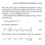
The point is that I'm puzzled by one thing. In his JAES article, May 1982, p. 302, he introduces some magic factor sqrt3 -1 (see pic), which should make the response "phase linear". If I use this magic factor (in stead of making the time constants just equal) I get overshoot. Now I've three questions:
1. Where did this magic factor come from? (btw, I have seen it elsewhere, but forgot where and in what context).
2. Is it possible to make a circuit phase linear and still get overshoot?
3. Or has Cherry just made a mistake?
I would be grateful if you could shed some light on these questions.
Cheers, E.
Hey Guru Zan,
You did read Cherry's papers on NDFL, didn't you?
The point is that I'm puzzled by one thing. In his JAES article, May 1982, p. 302, he introduces some magic factor sqrt3 -1 (see pic), which should make the response "phase linear". If I use this magic factor (in stead of making the time constants just equal) I get overshoot. Now I've three questions:
1. Where did this magic factor come from? (btw, I have seen it elsewhere, but forgot where and in what context).
2. Is it possible to make a circuit phase linear and still get overshoot?
3. Or has Cherry just made a mistake?
I would be grateful if you could shed some light on these questions.
Cheers, E.
Attachments
In a linear system the time domain response (like overshoot) is an exact transform of the frequency response
No, it does not.
The transform from the time domain to the frequency domain is just the Fourier transform.
Linearity is not a requirement for the Fourier transform. Non linear systems transform from time to frequency domain, and the other way around, just fine.
A pure sine signal passed through a nonlinear system will create at the output, in the frequency domain, only harmonic components.
- Status
- This old topic is closed. If you want to reopen this topic, contact a moderator using the "Report Post" button.
- Home
- Amplifiers
- Solid State
- TPC vs TMC vs 'pure Cherry'