power supplies for tpa3251d2
Again, since these are new - would it be possible to go with a 250W fanless PSU at 36V (or 24V?) and give up on max power for the sake of staying fanless? Or would the PSU shut off when played at full tilt? Or use dual PSUs?!
Power supplies are listed here in the thread, a MeanWell 36V 350W will do fine.
Again, since these are new - would it be possible to go with a 250W fanless PSU at 36V (or 24V?) and give up on max power for the sake of staying fanless? Or would the PSU shut off when played at full tilt? Or use dual PSUs?!
If it does your peak power demands, you should be fine.
The "NES-350-36" has fan-control, so forced cooling is only on t >=55°C.Similar performance, but fanless would be the "ERP-350-36". (But take note, that this supply is meant to be used outside upright - so maybe not what you're looking for.) The slightly better, regarding Vppnoise, "LRS-350-36" isn't fanless.
The "NES-350-36" has fan-control, so forced cooling is only on t >=55°C.Similar performance, but fanless would be the "ERP-350-36". (But take note, that this supply is meant to be used outside upright - so maybe not what you're looking for.) The slightly better, regarding Vppnoise, "LRS-350-36" isn't fanless.
Again, since these are new - would it be possible to go with a 250W fanless PSU at 36V (or 24V?) and give up on max power for the sake of staying fanless? Or would the PSU shut off when played at full tilt? Or use dual PSUs?!
I bought a Connexectronic SMPS600RS, 38V version. Rated at 600W, is more than enough power for the job, fanless and very small.
Connexelectronic
Probably the 300W SMPS300RS (36V) will be enough for 2 channel, but the price difference (including shipping,, which is expensive...) is not much and I assumed the power ratings are a bit 'optimistic' so wanted to stay on the safe side.
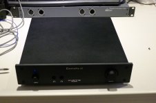
My amp with the TPA3251 and the SMPS600RS stays on all the time and has no air vents (I used an old DAC case I still had). The temperature of the case stays below 40 deg. C. (25C ambient temp) while playing music at normal volume levels.
Rob
What about the temp in the case?
That's a good question. I assumed it will be not much higher than the case temperature but when I think about it there might be hot spots.
I will measure the temperature in several places inside the case and post back the results.
Results
Hi,
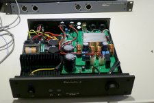
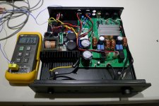
Did some measurement to find hot spots.
Method:
(a) open case
(b) place sensor
(c) replace cover
(d) play music for an hour on background music level (8 ohm speakers, 98dB @ 1W 1m)
(e) read temperature while still playing
Do (a-e) for every point.
Results:
Inside air, near to capacitor: 35.8 degrees
Heat sink SMPS : 44.3 degrees
Heat sink TPA3251 : 51.5 degrees
Ambient 23 C, Voltage on TPA3251 is 38V.
Some conclusions. Result are not bad for a low-profile closed case but I would not sell this as a solution to anyone as the TPA runs hotter than expected. A few holes in the case would go a long way.
Power supply really runs cool at low load, cooler than expected.
Hopefully useful.
Rob
Hi,
Did some measurement to find hot spots.
Method:
(a) open case
(b) place sensor
(c) replace cover
(d) play music for an hour on background music level (8 ohm speakers, 98dB @ 1W 1m)
(e) read temperature while still playing
Do (a-e) for every point.
Results:
Inside air, near to capacitor: 35.8 degrees
Heat sink SMPS : 44.3 degrees
Heat sink TPA3251 : 51.5 degrees
Ambient 23 C, Voltage on TPA3251 is 38V.
Some conclusions. Result are not bad for a low-profile closed case but I would not sell this as a solution to anyone as the TPA runs hotter than expected. A few holes in the case would go a long way.
Power supply really runs cool at low load, cooler than expected.
Hopefully useful.
Rob
Attachments
Well, would be interesting at higher continouse output levels. 55°C is nothing i'd worry about if the heatsink is having a low Rth. Would be of interested at what temperature the IC is on top.
But as the the enclosure is not vented in any way, thermal mass of the heatsink is also to note. Did you overmilled the contact surface?
But as the the enclosure is not vented in any way, thermal mass of the heatsink is also to note. Did you overmilled the contact surface?
But as the the enclosure is not vented in any way, thermal mass of the heatsink is also to note. Did you overmilled the contact surface?
Hi,
I use a standard heat sink, 2 mm spacers and fill up the gap between the chip and the heat sink with silicone thermal sheet (the stuff they use for GPU / CPU cooling interface in notebooks).
Like Blue 100mmx100mmx1mm GPU CPU Heatsink Cooling Thermal Conductive Silicone Pad | eBay
I can run 2x 100W into 4 Ohm (open case...) without the chip overheating.
The next version of the PCB I will put the decouple caps on the bottom of the PCB, much easier to mount the heat sink then.
Next in line of the TPA325x series and also following in the footsteps of Docs 'mini' amp. The TPA3250 helps with this significantly and in a lot of ways is far nicer than the TPA3251 unless you need the added output power.
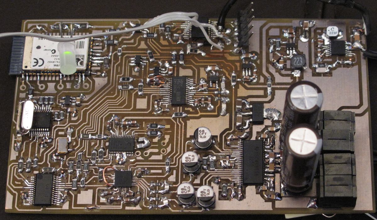
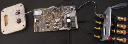
My main love of class D amplifiers and well modern electronics in general is the miniaturisation that is possible.
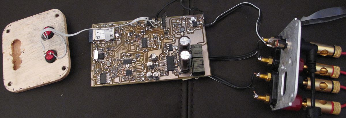
The PCB is 65x110mm but combines a bluetooth module, SPDIF receiver, ADC, ASRC, two DACs (with built in DSPs), the TPA3250 and the various power management chips.
One of the DAC chips is the PCM5242, this is a relatively new chip from TI and outputs a balanced signal. This is perfect as it allows it to interface directly with the TPA3250 without any SE>BAL converters. Obviously this signal path is designed to drive a pair of loudspeakers.
The second DAC is the SE version, the PCM5142 that came out some months before the 5242. They are essentially the same part and run on pretty much the same I2C code, save for the differences in the output configuration. This was included specifically for driving a subwoofer. One of the reasons I redesigned the system is because of a ground loop that appeared once I added the sub, which was rather unfortunate, still it gave me an opportunity to come up with this.
For the other chips, I used the PCM1861 ADC, the WM8804 SPDIF receiver, SRC4192 ASRC and the RN52 bluetooth module.
For power management I went with the LM46002 to step down the raw output voltage down to 14V. This feeds a LM2940 for the 12V supply on the TPA3250 and a TPS560200 to step the 14V down to ~4V before feeding several LP5907s that create the 3.3V needed for all of the other devices.
Measurements will hopefully be to follow!
My main love of class D amplifiers and well modern electronics in general is the miniaturisation that is possible.
The PCB is 65x110mm but combines a bluetooth module, SPDIF receiver, ADC, ASRC, two DACs (with built in DSPs), the TPA3250 and the various power management chips.
One of the DAC chips is the PCM5242, this is a relatively new chip from TI and outputs a balanced signal. This is perfect as it allows it to interface directly with the TPA3250 without any SE>BAL converters. Obviously this signal path is designed to drive a pair of loudspeakers.
The second DAC is the SE version, the PCM5142 that came out some months before the 5242. They are essentially the same part and run on pretty much the same I2C code, save for the differences in the output configuration. This was included specifically for driving a subwoofer. One of the reasons I redesigned the system is because of a ground loop that appeared once I added the sub, which was rather unfortunate, still it gave me an opportunity to come up with this.
For the other chips, I used the PCM1861 ADC, the WM8804 SPDIF receiver, SRC4192 ASRC and the RN52 bluetooth module.
For power management I went with the LM46002 to step down the raw output voltage down to 14V. This feeds a LM2940 for the 12V supply on the TPA3250 and a TPS560200 to step the 14V down to ~4V before feeding several LP5907s that create the 3.3V needed for all of the other devices.
Measurements will hopefully be to follow!
Attachments

What a mess.Congrats!
Haha indeed, it's a lot of silicon in such a small space. I had it all laid out without the ADC but there was board space left and I thought...well I've used the PCM1861 before and it will fit...so to it I went again.
I like your design and pcb with the 0 ohm jumpers = cool even the DFN, aren't they fun.
Amazing how much function we can put on a small pcb these days.
Zero ohm jumpers are my best friends
With only a dual layer PCB and such a complex routing of all the I2S lines it's inevitable. I would much rather go to town with zero ohm jumpers on the top side than interrupt the ground plane!Those DFNs are certainly a step up in soldering complexity. I am not really a fan of them but I have managed to figure out a decent way to hand solder them although they really do require the fine tip bit on the Metcal and lots of flux always helps.
I did a design with a 20 pin DFN, MAX9729. I learned that if you plan to hand solder you better open up the solder mask enough, so that you can get an iron tip on the trace to wick the solder into the package pad. tricky business for the faint of heart.
I like using the 15mil glow core no clean solder, Pb/Sn of coarse, the heck with ROHS
Care to share your schematic?
I like using the 15mil glow core no clean solder, Pb/Sn of coarse, the heck with ROHS
Care to share your schematic?
Last edited:
Screw ROHS I agree, there's nothing worse than trying to work with tin solder on tricky to solder parts. There's a reason why military and aerospace don't use lead free...it's terrible stuff really where reliability and difficult solder joints are involved.
Sadly I do not have a schematic I don't bother drawing them up, just working from datasheets and designing PCB layouts on the fly/writing stuff down that's necessary. Wiring up all of those parts is fairly basic stuff though just using the micro controller to program the DSPs/switching between sources/control the volume/handle resets etc.
Sadly I do not have a schematic I don't bother drawing them up, just working from datasheets and designing PCB layouts on the fly/writing stuff down that's necessary. Wiring up all of those parts is fairly basic stuff though just using the micro controller to program the DSPs/switching between sources/control the volume/handle resets etc.
Nice work. I hear you about DFN/QFN soldering, definitely a test for even those experienced with soldering and the ones without a soldering tag on the external vertical surface of the package are the worst - I changed my design / chip choice on one solution because I just couldn't get reliable joints (hot plate was the best way).
Apart from power & heatsink, in what way is the 3250 better than the 3251?
Apart from power & heatsink, in what way is the 3250 better than the 3251?
How do you like the PCM5242 and PCM1861? I am in the planning stages of a project involving that same DAC and a PCM1863 ADC. My main hang up right now is finding a suitable USB reciever, as I would like both the DAC and ADC to be visible to a PC over USB, preferably at their full resolutions. The SA9227 is quite promising, but I think the tool needed to program the EEPROM is a proprietary job you can only get if you buy volume and sign NDAs.
Output from the digital side would be going to a TPA6120 HP amp, and a TPA325x power amp. So somewhat similar to your board.
Output from the digital side would be going to a TPA6120 HP amp, and a TPA325x power amp. So somewhat similar to your board.
- Home
- Amplifiers
- Class D
- TPA3251d2