Here also a source of smps at the bottom of the page, but don't know about the quality... DIY / PCB
Thanks for the tip!
Especially the connexelectronic stuff looks good.
For those prices it's difficult to build it yourself... Will buy a few, probably directly from connexelectronic.com to see how they work.
From the bench, the amp is able to withstand 2x170W cont. sine wave (tested at 150,330,1000Hz) into 4R, tested for one hour at 20C. Inductors surface temperature settled at ~97C and is (thermally) the limiting factor. Bottom side of the heatsink next to the IC is at ~75C. The voltage supervisor needs some fine tuning but avoids any pop at hard power down. ")


Hello all,
I just finished reading through this thread. There are some very nice implementations of this amplifier.
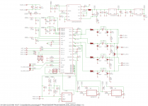
I am trying to build one myself. I would be very grateful if you can take a look of my final schematic. I closely based it on the EVAL board schematic. I want to run this board with single ended inputs BTL with the option to switch it to PBTL. Are the shunts near the output correct if I want to change it to PBTL?
Are there any show stoppers you guys see? Can you provide any additions and recommendations if you have any?
I know the board layout is very important with a class D amp. I also plan to closely follow the layout of the evaluation board. I want to see if there is anything wrong to the schematic due to my ignorance before I start the layout.
Thank you for your time!
I just finished reading through this thread. There are some very nice implementations of this amplifier.
I am trying to build one myself. I would be very grateful if you can take a look of my final schematic. I closely based it on the EVAL board schematic. I want to run this board with single ended inputs BTL with the option to switch it to PBTL. Are the shunts near the output correct if I want to change it to PBTL?
Are there any show stoppers you guys see? Can you provide any additions and recommendations if you have any?
I know the board layout is very important with a class D amp. I also plan to closely follow the layout of the evaluation board. I want to see if there is anything wrong to the schematic due to my ignorance before I start the layout.
Thank you for your time!
Attachments
My Notes:
- Have a spare resistor footprint avail on your board in parallel to C67, it may needs finetuning with a resistor int the range on 30-100k
- C84 is optional
- add series resistor to the reset input (right behind the header), M1, M2 (optional)
- increase Cstart to 100n
- route OC_IOP/N differentially
- route inputs differentially
- Your actual layout is for BTL/PBTL and SE, it this intented? If not, skip the 470uF caps at the output
- PBTL_SPK-X can be skipped, just need to parallel LEFT/RIGHT_SPK-X via solid wire or at the terminals
- add 100k pulldown to ~RESET
- add 100k pullup to ~MR (optional)
- Have TVS/Cera (5V6) diode in parallel to C67 to secure the SVS
- R1/R3 should be greater zero ohms to have the RC filter working
- rather than looking for high bulk capacitance, keep an eye on low ESR + ripple current. Capacitance is not the key factor here.
- D3 may be replaced with 0R
- C39 belongs to?
- C5 C9 changes place in the schematic (as C9 should be close to the LDO)
- C10 could be lowered to 1uF MLCC as there's only pullups + 1 led connected
- R30 should be greater zeros ohms (100-1k)
- C6 could be ceramic 1-2u2 should be sufficient
- check DC-bias (and capacitance derating loss) esspecially for C38, C32, C33, C47, C48, C4, C83
Last edited:
Doctormord,
Thank you for your time and recommendations. I am not debating whether I should add the differential inputs. I originally intended to have it default in SE input BTL mode with the option for PBTL.
C39 is a smoothing cap at the power input I would have to guess, I am not as well versed as I should be. It was part of the EVAL board.
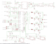
I have added your changes to the schematic. I think my interpretations of them are correct. Is this diode a suitable substitute to the one you recommended?
Also, what value resistor would you recommend that will be in series with the reset switch? I was thinking 5k.
Thanks again for your time!
Thank you for your time and recommendations. I am not debating whether I should add the differential inputs. I originally intended to have it default in SE input BTL mode with the option for PBTL.
C39 is a smoothing cap at the power input I would have to guess, I am not as well versed as I should be. It was part of the EVAL board.
I have added your changes to the schematic. I think my interpretations of them are correct. Is this diode a suitable substitute to the one you recommended?
Also, what value resistor would you recommend that will be in series with the reset switch? I was thinking 5k.
Thanks again for your time!
Attachments
Addition:
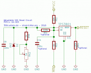
From my own experience, the SVS circuit is not the real deal. Maybe it works better with the LM5010 like on the EVM with its 2.5V Vfb, but with a low-margin buck converter like the LMR14206 or 16006 and a Vfb of only 0.7V it's a bit of PITA.
The function is depends on the ramp down time of your power supply and the value of Cstart. Smaller values of Cstart ramps down the 3251 faster in case you pulled the ~RESET line. MUTE isn't working immediately but with a ramp.
For the SVS, the speed-up cap from PVCC to the voltage-divider at the TPS "should" trip at PVCC power loss fast but also should not false-trip. The standard configuration from the EVM isn't working great with a LMR16006 as it does not trip correctly if your PVCC power-down-ramp is low (limited by the bulk caps and actual output power), like broken/pulled connector at high voltages. Interestingly it works for lower PVCC-voltages.
Worst case for power-loss is at zero input signal.
If you then lower the monitoring-voltage by having a parallel resistor to GND (parallel to C67 in your schematic) it works correct for power-loss/power-off but makes the circuit sensitive to false-trips by PVCC voltage variation. (at high power output levels near clipping)
You will also have to take the variation of Vth (Threshold voltage) into account, which is 2.87 - 2.99V for the TPS3801. So if it works on one board, it might not do on another.
From TI tech support:
To be fair, i've test the "pop-situation" with a 15" 104dB/w bass-chassis.
From my own experience, the SVS circuit is not the real deal. Maybe it works better with the LM5010 like on the EVM with its 2.5V Vfb, but with a low-margin buck converter like the LMR14206 or 16006 and a Vfb of only 0.7V it's a bit of PITA.
The function is depends on the ramp down time of your power supply and the value of Cstart. Smaller values of Cstart ramps down the 3251 faster in case you pulled the ~RESET line. MUTE isn't working immediately but with a ramp.
For the SVS, the speed-up cap from PVCC to the voltage-divider at the TPS "should" trip at PVCC power loss fast but also should not false-trip. The standard configuration from the EVM isn't working great with a LMR16006 as it does not trip correctly if your PVCC power-down-ramp is low (limited by the bulk caps and actual output power), like broken/pulled connector at high voltages. Interestingly it works for lower PVCC-voltages.
Worst case for power-loss is at zero input signal.
If you then lower the monitoring-voltage by having a parallel resistor to GND (parallel to C67 in your schematic) it works correct for power-loss/power-off but makes the circuit sensitive to false-trips by PVCC voltage variation. (at high power output levels near clipping)
You will also have to take the variation of Vth (Threshold voltage) into account, which is 2.87 - 2.99V for the TPS3801. So if it works on one board, it might not do on another.
From TI tech support:
So it most likely will work if you take their buck-converter-ic but this also depends on your power supply and bulk caps.Power supply supervisor: We tuned the capacitive divider (R61,C83,C84) on the TPA3251D2 EVM supervisory circuit to respond quickly to a falling supply, but not to trip falsely due to small power supply dips. You may want to tweak R61 lower to give a more advance warning to negative PSU dV/dt. The goal is to let the IC start shutting down (ramping down gracefully, using Cstart) as soon as possible while the power supply is still above 18V or so. If the power supply goes below ~9V before the ramp is completed, the Undervoltage threshold will cause a fault and shut the output off suddenly, resulting in a pop. Cstart plays a role here as well. Lower Cstart will make shutdown ramp faster, so in BTL mode you get less chance of a UV fault before the ramp is done at the expense of lower PSRR.
To be fair, i've test the "pop-situation" with a 15" 104dB/w bass-chassis.
Last edited:
Replying to your schematic at post #670:
Maybe you misunderstood the part i'm refering to "SE". The 470uF caps (C21, C34, C42, C46) are for SE output, so having 4 output channels. If you only want to have the board in BTL (2 channel) or PBTL (1 channel), you don't need them ( replace with straight line/wire in schematic).
The schematic misses the AFE (analog frontend) where you do SE-to-DIFF for the inputs, so you feeding already differential signals into the amp from another Gain/Buffer section?
Reset switch resistor is just 1k or so. Exact value does't matter as long as your manual reset can pull down the pin. So everything <10k is okay. The main reason is safety to limit the current when spikes apply to this pin(header).
For the diode, i normally use Cera-Diodes (5V6 high-speed) in 0402. If you feel more comfortable with 0603 it's this:
0603:
Part#: B72500D0050H160
Mouser#: 871-B72500D0050H160
0402:
Part#: B72590D50H160
Mouser#: 871-B72590D50H160
A normal zener "might" do but isn't that sharp limiting and slow - not recommended here. For the Cera-Diodes take a capacitor-footprint of the same size, will fit. (But as i don't know the standard Eagle footprint library this should be checked.)
From the EVM layout, C39 (47uF 50V) belongs to the buck-converter so you may move this over to this section as it needs to be close to this on the board also. C3+C11 belongs to the SVS (Supply Voltage Supervisor) and should be keeped together with R61.
Edit:
C10 is still 100uF. No problem with that, but could be lowered as noted already.
Maybe you misunderstood the part i'm refering to "SE". The 470uF caps (C21, C34, C42, C46) are for SE output, so having 4 output channels. If you only want to have the board in BTL (2 channel) or PBTL (1 channel), you don't need them ( replace with straight line/wire in schematic).
The schematic misses the AFE (analog frontend) where you do SE-to-DIFF for the inputs, so you feeding already differential signals into the amp from another Gain/Buffer section?
Reset switch resistor is just 1k or so. Exact value does't matter as long as your manual reset can pull down the pin. So everything <10k is okay. The main reason is safety to limit the current when spikes apply to this pin(header).
For the diode, i normally use Cera-Diodes (5V6 high-speed) in 0402. If you feel more comfortable with 0603 it's this:
0603:
Part#: B72500D0050H160
Mouser#: 871-B72500D0050H160
0402:
Part#: B72590D50H160
Mouser#: 871-B72590D50H160
A normal zener "might" do but isn't that sharp limiting and slow - not recommended here. For the Cera-Diodes take a capacitor-footprint of the same size, will fit. (But as i don't know the standard Eagle footprint library this should be checked.)
From the EVM layout, C39 (47uF 50V) belongs to the buck-converter so you may move this over to this section as it needs to be close to this on the board also. C3+C11 belongs to the SVS (Supply Voltage Supervisor) and should be keeped together with R61.
Edit:
C10 is still 100uF.
No problem with that, but could be lowered as noted already.
Last edited:
Doctormord,
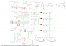
Ah, forgive my misunderstanding. I just plan to skip the AFE and just connect the single ended RCA to the LEFT_IN_X and RIGHT_IN_X. And to run in PBTL, I can just parallel the speaker terminals and ground input C and D via the PBTL_GND jumpers. I am under the impression that this would work?
Thank you for the insight on the SVS circuit. I will pay more attention to this to have minimal pop. My speakers are not very sensitive. Since my schematic is a carbon copy of the EVM, I am hoping that the SVS circuit has satisfactory performance as is. However, I am keeping the 5v6 diode and your other recommendations and will order extra cap/resistors values for cstart and to fine tune if necessary.
I would keep this in mind as I work on the board layout.
Also, are you using 22uH inductors in the output filters (via your project site and photos)? I have some leftover Coilcraft SER2918s that I would like to use. Datasheet recommends 15uH so I figured 22uH would not be a problem for 8R load.
Thank you for your assistance and patience.
Maybe you misunderstood the part i'm refering to "SE". The 470uF caps (C21, C34, C42, C46) are for SE output, so having 4 output channels. If you only want to have the board in BTL (2 channel) or PBTL (1 channel), you don't need them ( replace with straight line/wire in schematic).
The schematic misses the AFE (analog frontend) where you do SE-to-DIFF for the inputs, so you feeding already differential signals into the amp from another Gain/Buffer section?
Ah, forgive my misunderstanding. I just plan to skip the AFE and just connect the single ended RCA to the LEFT_IN_X and RIGHT_IN_X. And to run in PBTL, I can just parallel the speaker terminals and ground input C and D via the PBTL_GND jumpers. I am under the impression that this would work?
Thank you for the insight on the SVS circuit. I will pay more attention to this to have minimal pop. My speakers are not very sensitive. Since my schematic is a carbon copy of the EVM, I am hoping that the SVS circuit has satisfactory performance as is. However, I am keeping the 5v6 diode and your other recommendations and will order extra cap/resistors values for cstart and to fine tune if necessary.
From the EVM layout, C39 (47uF 50V) belongs to the buck-converter so you may move this over to this section as it needs to be close to this on the board also. C3+C11 belongs to the SVS (Supply Voltage Supervisor) and should be keeped together with R61.
I would keep this in mind as I work on the board layout.
I kept that value as I already have the part. I will keep your note in mind.C10 is still 100uF.
Also, are you using 22uH inductors in the output filters (via your project site and photos)? I have some leftover Coilcraft SER2918s that I would like to use. Datasheet recommends 15uH so I figured 22uH would not be a problem for 8R load.
Thank you for your assistance and patience.
Attachments
Ah, forgive my misunderstanding. I just plan to skip the AFE and just connect the single ended RCA to the LEFT_IN_X and RIGHT_IN_X. And to run in PBTL, I can just parallel the speaker terminals and ground input C and D via the PBTL_GND jumpers. I am under the impression that this would work?
That does not work, the amp needs fully differential drive. That's different from the 3116/18 etc. So you'll need a SE-2-Diff stage in front with some additional gain.
Also, are you using 22uH inductors in the output filters (via your project site and photos)? I have some leftover Coilcraft SER2918s that I would like to use. Datasheet recommends 15uH so I figured 22uH would not be a problem for 8R load.
I use 10uH inductors with 1uF.
22uH + 680nF should do.
With the data from SER2918:
Thank you for your assistance and patience.
Cheers.
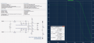
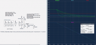
If you want to play around with the SVS, please see the attached LTspice .asc.
Attachments
Hi All,
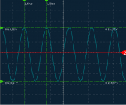
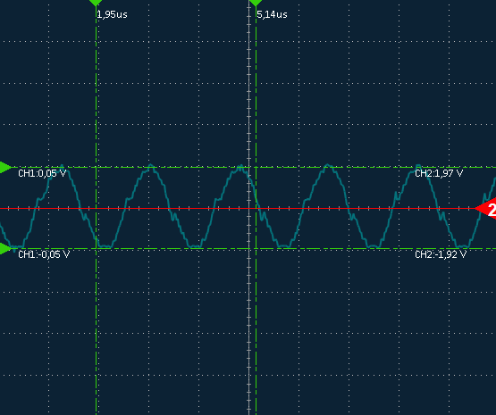
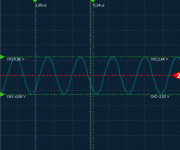
Builds are looking great! I was wondering if anyone can share their typical switching frequency residual at the output terminals after the LP filter. I'm getting around 170mV peak to peak, 10uH and 680nF.
Thanks
Im getting:
At PVCC=34V into 4R:
~250mVpp with a simplified filter and 10uH (GA3416) + 1uF MKP (Cstart=100n)
~800mVpp with a full reconstruction filter and 10uH (MSS1278) + 1uF MKT (Cstart=10n)
~500mVpp with a full reconstruction filter and 10uH (VER2923) + 1uF MKT (Cstart=10n)
At PVCC=18V into 4R:
~130mVpp with a simplified filter and 10uH (GA3416) + 1uF MKP (Cstart=100n)
~450mVpp with a full reconstruction filter and 10uH (MSS1278) + 1uF MKT (Cstart=10n)
~240mVpp with a full reconstruction filter and 10uH (VER2923) + 1uF MKT (Cstart=10n)
While this scales with PVCC i suspect the value of Cstart, the ESR of the bulk and output filter caps + parasitic inductance of traces have an impact as well.
Attachments
Last edited:
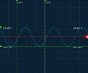
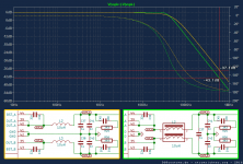
When modifying this:
~240mVpp with a full reconstruction filter and 10uH (MSS1278) + 1uF MKT (Cstart=10n)
for the simplified filter, it goes like this:
~124mVpp with a simplified filter and 10uH (MSS1278) + 1uF MKT (Cstart=10n)
So whats difference?

To behave the full filter like the the simplified filter, C needs to be increased to 2uF each.
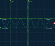
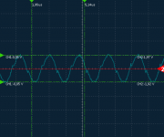
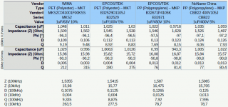
Changing the cap type also changes the residual.
Wima MKS2 1uF 63V(MKT):
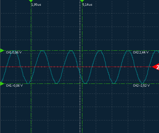
CBB22 1uF 400V(MKP):
Epcos 1uF 450V (MKP):

This wont be seen from the parameters if you measure your caps only up to 100kHz:

~240mVpp with a full reconstruction filter and 10uH (MSS1278) + 1uF MKT (Cstart=10n)
for the simplified filter, it goes like this:
~124mVpp with a simplified filter and 10uH (MSS1278) + 1uF MKT (Cstart=10n)
So whats difference?
To behave the full filter like the the simplified filter, C needs to be increased to 2uF each.
Changing the cap type also changes the residual.
Wima MKS2 1uF 63V(MKT):
CBB22 1uF 400V(MKP):
Epcos 1uF 450V (MKP):
This wont be seen from the parameters if you measure your caps only up to 100kHz:
Attachments
Last edited:
Hi Doc,
Thanks for the post, it was very helpful! Seems like everything is behaving as expected. The difference can be explained by the different PVCC being used. Will have to try increasing Cstart, good tip. The rest is a trade-off between peaking and noise.
Will hopefully get a chance to put this in the system by next weekend. Will report back on subjective results. Currently have TPA3118 in system.
Cheers,

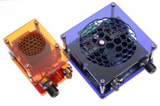
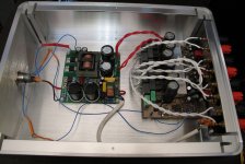
With the talk of the Connexelectronics SMPS and Hifimediy I figured I'd take the plunge and give one a go with my 6 channel TPA3251 build.
I went for the 300 watt 38volt version that was available and fine tuned the output voltage down to 36V.

The PSU is positively tiny and very light. I had wanted to try building my own LLC converter but considering the challenge involved, plus my need for the PSU now rather than later, due to additional requirements elsewhere, I figured it made sense to buy one. They aren't that expensive either which is a huge bonus.
And I added a nice switch to the front.
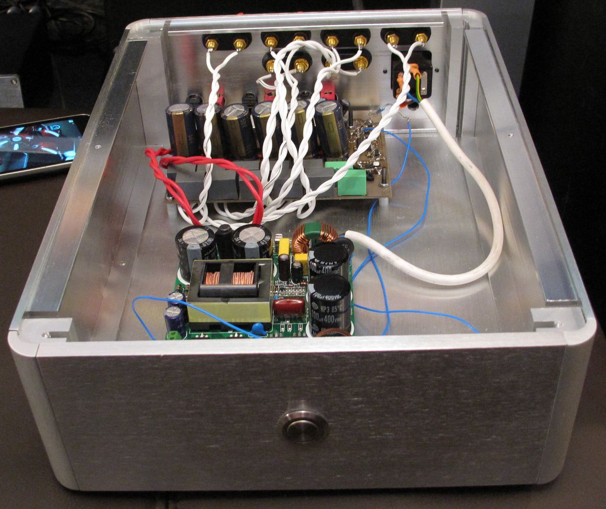
Everything appears to work very well. The AUX voltage is 12.5v for this model in case anyone is wondering.
I went for the 300 watt 38volt version that was available and fine tuned the output voltage down to 36V.
The PSU is positively tiny and very light. I had wanted to try building my own LLC converter but considering the challenge involved, plus my need for the PSU now rather than later, due to additional requirements elsewhere, I figured it made sense to buy one. They aren't that expensive either which is a huge bonus.
And I added a nice switch to the front.
Everything appears to work very well. The AUX voltage is 12.5v for this model in case anyone is wondering.
Attachments

- Home
- Amplifiers
- Class D
- TPA3251d2